


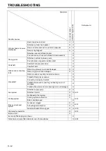


11
11-11
•
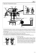
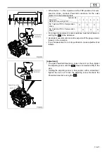
As the Powertard cam further rotates
and the cam lobe top leaves the mas-
ter piston, the oil pressure in the oil
passage is reduced.
•
As a result, the exhaust valve is
closed by its spring force, which allows
the valve to open and close according
to ordinary valve timing. At the same
time, the check valve in the control
valve opens to let engine oil (oil pres-
sure produced by ordinary engine oil
pump) work through the oil passages
and, allowing the exhaust valve to be
forced open again through the move-
ment of the Powertard cam.
•
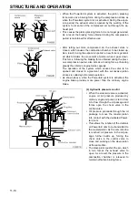
When the Powertard release condi-
tions are met, the following sequence
of operation is followed.
•
When the solenoid valve is de-ener-
gized, the control valve shuts the in-
coming path (A) for engine oil from
the rocker case and opens the out-
going path (B) to the cylinder head.
•
Engine oil in the oil passage is let
out through B, relieving the control
valve of oil pressure.
•
The control valve opens the path
(C) that has been closed by oil pres-
sure to let out engine oil in the
chamber of the slave piston and oil
passage.
•
As the oil pressure is removed, the
master piston is lowered to leave
the Powertard cam.
•
At the same time, the slave piston is
forced up by the spring force. As a
result, the exhaust valve is closed
and the Powertard is turned off.
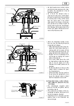
(3) Powertard brake control (Power-
tard: Switch is placed in the sec-
ond stage)
•
The turbocharger magnetic valve
feeds air A to the air cylinder, narrow-
ing turbine vane B.
•
The number of revolutions of the tur-
bocharger increases, taking more air
into the combustion chamber.
•
Compressed air C increases and the
braking force of the Powertard be-
comes stronger.
Содержание 6M70
Страница 29: ...M E M O 11 19 11 ...
Страница 35: ...M E M O 11 25 11 ...
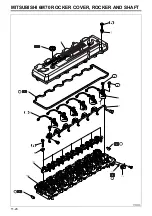
Страница 36: ...11 26 MITSUBISHI 6M70 ROCKER COVER ROCKER AND SHAFT ...
Страница 40: ...11 30 MITSUBISHI 6M70 CAMSHAFT AND ROCKER CASE ...
Страница 47: ...M E M O 11 37 11 ...
Страница 48: ...11 38 MITSUBISHI 6M70 CYLINDER HEAD AND VALVE MECHANISM ...
Страница 63: ...M E M O 11 53 11 ...
Страница 71: ...M E M O 11 61 11 ...
Страница 77: ...M E M O 11 67 11 ...
Страница 81: ...M E M O 11 71 11 ...
Страница 98: ...11 88 MITSUBISHI 6M70 CRANKSHAFT AND CRANKCASE ...
Страница 127: ...M E M O 12 21 12 ...
Страница 129: ...M E M O 12 23 12 ...
Страница 135: ...M E M O 13 3 13 ...
Страница 138: ...13 6 1 1 Mitsubishi 6M70 Supply pump STRUCTURE AND OPERATION ...
Страница 150: ...13 18 10 Electronic control unit connection diagram STRUCTURE AND OPERATION ...
Страница 151: ...13 13 19 ...
Страница 155: ...M E M O 13 23 13 ...
Страница 185: ...M E M O 13 53 13 ...
Страница 189: ...M E M O 13 57 13 ...
Страница 205: ...M E M O 13 73 13 ...
Страница 211: ...M E M O 13 79 13 ...
Страница 215: ...M E M O 13 83 13 ...
Страница 219: ...M E M O 13 87 13 ...
Страница 225: ...M E M O 13 93 13 ...
Страница 226: ...13 94 INSTALLED LOCATIONS OF PARTS ...
Страница 227: ...13 13 95 ...
Страница 228: ...13 96 INSTALLED LOCATIONS OF PARTS ...
Страница 229: ...13 13 97 ...
Страница 230: ...13 98 INSTALLED LOCATIONS OF PARTS ...
Страница 231: ...13 13 99 ...
Страница 232: ...13 100 MITSUBISHI 6M70 INSTALLED LOCATIONS OF PARTS ...
Страница 233: ...13 13 101 ...
Страница 234: ...13 102 ELECTRIC CIRCUIT DIAGRAM ...
Страница 235: ...13 13 103 ...
Страница 236: ...13 104 ELECTRIC CIRCUIT DIAGRAM ...
Страница 237: ...13 13 105 ...
Страница 238: ...13 106 ELECTRIC CIRCUIT DIAGRAM ...
Страница 241: ...14 14 3 1 Mitsubishi 6M70 Cooling System Flow of Coolant STRUCTURE AND OPERATION ...
Страница 252: ...14 14 Periphery of Engine DISCONNECTION AND CONNECTION OF HOSES AND PIPES ...
Страница 271: ...M E M O 14 33 14 ...
Страница 286: ...M E M O 15 13 15 ...
Страница 295: ...15 22 7 Installed Locations of Parts TURBOCHARGER CONTROL SYSTEM ...
Страница 296: ...15 15 23 ...
Страница 297: ...15 24 TURBOCHARGER CONTROL SYSTEM ...
Страница 298: ...15 15 25 ...
Страница 299: ...15 26 TURBOCHARGER CONTROL SYSTEM ...
Страница 300: ...15 15 27 ...
Страница 301: ...15 28 TURBOCHARGER CONTROL SYSTEM ...
Страница 302: ...M E M O 15 29 15 ...
Страница 303: ...15 30 8 Electric Circuit Diagram TURBOCHARGER CONTROL SYSTEM ...
Страница 304: ...15 15 31 ...
Страница 305: ...15 32 TURBOCHARGER CONTROL SYSTEM ...
Страница 306: ...M E M O 15 33 15 ...
Страница 330: ...M E M O 15 57 15 ...
Страница 340: ...17 6 1 3 Electronic control unit connection diagram STRUCTURE AND OPERATION ...
Страница 343: ...M E M O 17 9 17 ...
Страница 351: ...M E M O 17 17 17 ...
Страница 352: ...17 18 8 Installed Locations of Parts EXHAUST GAS RECIRCULATION SYSTEM ...
Страница 353: ...17 17 19 ...
Страница 354: ...17 20 EXHAUST GAS RECIRCULATION SYSTEM ...
Страница 355: ...17 17 21 ...
Страница 356: ...17 22 EXHAUST GAS RECIRCULATION SYSTEM ...
Страница 357: ...17 17 23 ...
Страница 358: ...17 24 9 Electric Circuit Diagram EXHAUST GAS RECIRCULATION SYSTEM ...
Страница 359: ...17 17 25 ...
Страница 360: ...17 26 MITSUBISHI 6M70 EGR VALVE EGR MAGNETIC VALVE EGR PIPE AND EGR COOLER ...


