


13-56
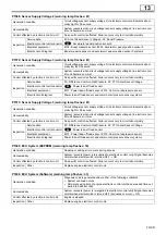
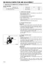
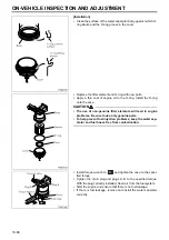
Output voltage of idling speed adjustment
potentiometer
[Conditions]
•
Starter switch ON
•
Vehicle-side harness connected (Perform inspection on back of connector.)
[Requirements]
Terminals (+)-(–): A12-A36
•
AUTO position: 4.0 ± 0.1 V
•
SLOW position: 3.0 ± 0.2 V
•
FAST position: 1.0 ± 0.1 V
Operating voltage of accelerator pedal switch
[Conditions]
•
Starter switch OFF
•
Disconnect connector. Perform inspection on vehicle-side connector.
[Requirements]
Terminals (+)-(–): A20-chassis ground
•
With accelerator pedal pressed: There is no continuity.
•
With accelerator pedal not pressed: There is continuity.
Resistance of fuel injection rate adjustment
resistor
[Conditions]
•
Starter switch OFF
•
Disconnect connector. Perform inspection on vehicle-side connector.
[Requirements]
Terminals: A35-A88
•
No. 1 resistor: 270 ± 13.5
Ω
•
No. 2 resistor: 510 ± 25.5
Ω
•
No. 3 resistor: 820 ± 41
Ω
•
No. 4 resistor: 1300 ± 65
Ω
•
No. 5 resistor: 2000 ± 100
Ω
•
No. 6 resistor: 3300 ± 165
Ω
•
No. 7 resistor: 5600 ± 280
Ω
•
No. 8 resistor: 15000 ± 750
Ω
•
No. 9 resistor: 390 ± 19.5
Ω
•
No. 10 resistor: 4300 ± 215
Ω
•
No. 11 resistor: 9100 ± 455
Ω
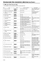
Resistance of Power take-off resistor
[Conditions]
•
Starter switch OFF
•
Disconnect connector. Perform inspection on vehicle-side connector.
[Requirements]
Terminals: A43-A19
•
No. 1 resistor: 270 ± 13.5
Ω
•
No. 2 resistor: 510 ± 25.5
Ω
•
No. 3 resistor: 820 ± 41
Ω
•
No. 4 resistor: 1300 ± 65
Ω
•
No. 5 resistor: 2000 ± 100
Ω
•
No. 6 resistor: 3300 ± 165
Ω
•
No. 7 resistor: 5600 ± 280
Ω
•
No. 8 resistor: 15000 ± 750
Ω
Resistance of MPROP
(rail pressure control valve)
[Conditions]
•
Starter switch OFF
•
Disconnect connector. Perform inspection on vehicle-side connector.
[Requirements]
Terminals:
•
A69-A21, A69-A2, A3-A21, A3-A2 (MPROP1)
•
A27-A4, A27-B38, B52-A4, B52-B38 (MPROP2)
•
2.6 to 3.15
Ω
Voltage of Powertard solenoid valve
[Conditions]
•
Starter switch OFF
•
Disconnect connector. Perform inspection on vehicle-side connector.
[Requirements]
Terminals: A74-A5
•
32.6 to 39.8
Ω
(engine oil temperature: 25
°
C)
Resistance of controller area network resistor
[Conditions]
•
Starter switch OFF
•
Disconnect connector. Perform inspection on vehicle-side connector.
[Requirements]
Terminals: B11-B12, B5-B6
•
120 ± 6
Ω
10
11
12
13
14
15
16
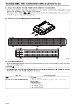
TROUBLESHOOTING <DIAGNOSIS USING Multi-Use Tester>
Содержание 6M70
Страница 29: ...M E M O 11 19 11 ...
Страница 35: ...M E M O 11 25 11 ...
Страница 36: ...11 26 MITSUBISHI 6M70 ROCKER COVER ROCKER AND SHAFT ...
Страница 40: ...11 30 MITSUBISHI 6M70 CAMSHAFT AND ROCKER CASE ...
Страница 47: ...M E M O 11 37 11 ...
Страница 48: ...11 38 MITSUBISHI 6M70 CYLINDER HEAD AND VALVE MECHANISM ...
Страница 63: ...M E M O 11 53 11 ...
Страница 71: ...M E M O 11 61 11 ...
Страница 77: ...M E M O 11 67 11 ...
Страница 81: ...M E M O 11 71 11 ...
Страница 98: ...11 88 MITSUBISHI 6M70 CRANKSHAFT AND CRANKCASE ...
Страница 127: ...M E M O 12 21 12 ...
Страница 129: ...M E M O 12 23 12 ...
Страница 135: ...M E M O 13 3 13 ...
Страница 138: ...13 6 1 1 Mitsubishi 6M70 Supply pump STRUCTURE AND OPERATION ...
Страница 150: ...13 18 10 Electronic control unit connection diagram STRUCTURE AND OPERATION ...
Страница 151: ...13 13 19 ...
Страница 155: ...M E M O 13 23 13 ...
Страница 185: ...M E M O 13 53 13 ...
Страница 189: ...M E M O 13 57 13 ...
Страница 205: ...M E M O 13 73 13 ...
Страница 211: ...M E M O 13 79 13 ...
Страница 215: ...M E M O 13 83 13 ...
Страница 219: ...M E M O 13 87 13 ...
Страница 225: ...M E M O 13 93 13 ...
Страница 226: ...13 94 INSTALLED LOCATIONS OF PARTS ...
Страница 227: ...13 13 95 ...
Страница 228: ...13 96 INSTALLED LOCATIONS OF PARTS ...
Страница 229: ...13 13 97 ...
Страница 230: ...13 98 INSTALLED LOCATIONS OF PARTS ...
Страница 231: ...13 13 99 ...
Страница 232: ...13 100 MITSUBISHI 6M70 INSTALLED LOCATIONS OF PARTS ...
Страница 233: ...13 13 101 ...
Страница 234: ...13 102 ELECTRIC CIRCUIT DIAGRAM ...
Страница 235: ...13 13 103 ...
Страница 236: ...13 104 ELECTRIC CIRCUIT DIAGRAM ...
Страница 237: ...13 13 105 ...
Страница 238: ...13 106 ELECTRIC CIRCUIT DIAGRAM ...
Страница 241: ...14 14 3 1 Mitsubishi 6M70 Cooling System Flow of Coolant STRUCTURE AND OPERATION ...
Страница 252: ...14 14 Periphery of Engine DISCONNECTION AND CONNECTION OF HOSES AND PIPES ...
Страница 271: ...M E M O 14 33 14 ...
Страница 286: ...M E M O 15 13 15 ...
Страница 295: ...15 22 7 Installed Locations of Parts TURBOCHARGER CONTROL SYSTEM ...
Страница 296: ...15 15 23 ...
Страница 297: ...15 24 TURBOCHARGER CONTROL SYSTEM ...
Страница 298: ...15 15 25 ...
Страница 299: ...15 26 TURBOCHARGER CONTROL SYSTEM ...
Страница 300: ...15 15 27 ...
Страница 301: ...15 28 TURBOCHARGER CONTROL SYSTEM ...
Страница 302: ...M E M O 15 29 15 ...
Страница 303: ...15 30 8 Electric Circuit Diagram TURBOCHARGER CONTROL SYSTEM ...
Страница 304: ...15 15 31 ...
Страница 305: ...15 32 TURBOCHARGER CONTROL SYSTEM ...
Страница 306: ...M E M O 15 33 15 ...
Страница 330: ...M E M O 15 57 15 ...
Страница 340: ...17 6 1 3 Electronic control unit connection diagram STRUCTURE AND OPERATION ...
Страница 343: ...M E M O 17 9 17 ...
Страница 351: ...M E M O 17 17 17 ...
Страница 352: ...17 18 8 Installed Locations of Parts EXHAUST GAS RECIRCULATION SYSTEM ...
Страница 353: ...17 17 19 ...
Страница 354: ...17 20 EXHAUST GAS RECIRCULATION SYSTEM ...
Страница 355: ...17 17 21 ...
Страница 356: ...17 22 EXHAUST GAS RECIRCULATION SYSTEM ...
Страница 357: ...17 17 23 ...
Страница 358: ...17 24 9 Electric Circuit Diagram EXHAUST GAS RECIRCULATION SYSTEM ...
Страница 359: ...17 17 25 ...
Страница 360: ...17 26 MITSUBISHI 6M70 EGR VALVE EGR MAGNETIC VALVE EGR PIPE AND EGR COOLER ...