


11-96
•
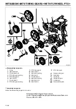
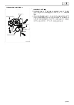
Starting at the front of the engine, fit the main bearing caps in the
order of the embossed numbers with the embossed numbers
and front marks facing in the illustrated direction.
•
Tighten all the bolts to 100 N·m {10 kgf·m}, then additionally
tighten them according in the following procedure.
•
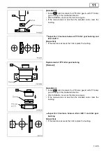
Turn the holder of
counterclockwise to pretension the inter-
nal spring.
•
Set the tool such that the rod (extension) is pressed against the
crankcase by the force of the spring.
•
Align any line on the holder scale with any line on the socket
scale. (This will be used as the reference point = 0
°
.)
•
From the reference point, turn the socket by 130
°
in the direction
shown. Each division on the socket scale represents 5
°
.
•
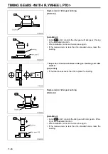
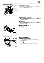
After tightening the bolt within the plastic region, make a punch
mark on the bolt head to record the number of times that they
have been tightened
CAUTION
• The bolts should be tightened within the plastic region.
Never tighten them further than the specified angle.
•
After tightening the bolt, rotate the crankshaft by hand. If it can-
not be rotated smoothly, inspect the main bearing cap for mount-
ing surface.
Installation:
Mitsubishi 6M70
Front oil seal
•
Install the front oil seal onto the front cover while pressing the
seal’s entire periphery evenly to prevent it from tilting.
•
Install the front oil seal until its flange comes into positive contact
with the front cover.
CRANKSHAFT AND CRANKCASE
Содержание 6M70
Страница 29: ...M E M O 11 19 11 ...
Страница 35: ...M E M O 11 25 11 ...
Страница 36: ...11 26 MITSUBISHI 6M70 ROCKER COVER ROCKER AND SHAFT ...
Страница 40: ...11 30 MITSUBISHI 6M70 CAMSHAFT AND ROCKER CASE ...
Страница 47: ...M E M O 11 37 11 ...
Страница 48: ...11 38 MITSUBISHI 6M70 CYLINDER HEAD AND VALVE MECHANISM ...
Страница 63: ...M E M O 11 53 11 ...
Страница 71: ...M E M O 11 61 11 ...
Страница 77: ...M E M O 11 67 11 ...
Страница 81: ...M E M O 11 71 11 ...
Страница 98: ...11 88 MITSUBISHI 6M70 CRANKSHAFT AND CRANKCASE ...
Страница 127: ...M E M O 12 21 12 ...
Страница 129: ...M E M O 12 23 12 ...
Страница 135: ...M E M O 13 3 13 ...
Страница 138: ...13 6 1 1 Mitsubishi 6M70 Supply pump STRUCTURE AND OPERATION ...
Страница 150: ...13 18 10 Electronic control unit connection diagram STRUCTURE AND OPERATION ...
Страница 151: ...13 13 19 ...
Страница 155: ...M E M O 13 23 13 ...
Страница 185: ...M E M O 13 53 13 ...
Страница 189: ...M E M O 13 57 13 ...
Страница 205: ...M E M O 13 73 13 ...
Страница 211: ...M E M O 13 79 13 ...
Страница 215: ...M E M O 13 83 13 ...
Страница 219: ...M E M O 13 87 13 ...
Страница 225: ...M E M O 13 93 13 ...
Страница 226: ...13 94 INSTALLED LOCATIONS OF PARTS ...
Страница 227: ...13 13 95 ...
Страница 228: ...13 96 INSTALLED LOCATIONS OF PARTS ...
Страница 229: ...13 13 97 ...
Страница 230: ...13 98 INSTALLED LOCATIONS OF PARTS ...
Страница 231: ...13 13 99 ...
Страница 232: ...13 100 MITSUBISHI 6M70 INSTALLED LOCATIONS OF PARTS ...
Страница 233: ...13 13 101 ...
Страница 234: ...13 102 ELECTRIC CIRCUIT DIAGRAM ...
Страница 235: ...13 13 103 ...
Страница 236: ...13 104 ELECTRIC CIRCUIT DIAGRAM ...
Страница 237: ...13 13 105 ...
Страница 238: ...13 106 ELECTRIC CIRCUIT DIAGRAM ...
Страница 241: ...14 14 3 1 Mitsubishi 6M70 Cooling System Flow of Coolant STRUCTURE AND OPERATION ...
Страница 252: ...14 14 Periphery of Engine DISCONNECTION AND CONNECTION OF HOSES AND PIPES ...
Страница 271: ...M E M O 14 33 14 ...
Страница 286: ...M E M O 15 13 15 ...
Страница 295: ...15 22 7 Installed Locations of Parts TURBOCHARGER CONTROL SYSTEM ...
Страница 296: ...15 15 23 ...
Страница 297: ...15 24 TURBOCHARGER CONTROL SYSTEM ...
Страница 298: ...15 15 25 ...
Страница 299: ...15 26 TURBOCHARGER CONTROL SYSTEM ...
Страница 300: ...15 15 27 ...
Страница 301: ...15 28 TURBOCHARGER CONTROL SYSTEM ...
Страница 302: ...M E M O 15 29 15 ...
Страница 303: ...15 30 8 Electric Circuit Diagram TURBOCHARGER CONTROL SYSTEM ...
Страница 304: ...15 15 31 ...
Страница 305: ...15 32 TURBOCHARGER CONTROL SYSTEM ...
Страница 306: ...M E M O 15 33 15 ...
Страница 330: ...M E M O 15 57 15 ...
Страница 340: ...17 6 1 3 Electronic control unit connection diagram STRUCTURE AND OPERATION ...
Страница 343: ...M E M O 17 9 17 ...
Страница 351: ...M E M O 17 17 17 ...
Страница 352: ...17 18 8 Installed Locations of Parts EXHAUST GAS RECIRCULATION SYSTEM ...
Страница 353: ...17 17 19 ...
Страница 354: ...17 20 EXHAUST GAS RECIRCULATION SYSTEM ...
Страница 355: ...17 17 21 ...
Страница 356: ...17 22 EXHAUST GAS RECIRCULATION SYSTEM ...
Страница 357: ...17 17 23 ...
Страница 358: ...17 24 9 Electric Circuit Diagram EXHAUST GAS RECIRCULATION SYSTEM ...
Страница 359: ...17 17 25 ...
Страница 360: ...17 26 MITSUBISHI 6M70 EGR VALVE EGR MAGNETIC VALVE EGR PIPE AND EGR COOLER ...


