


17-10
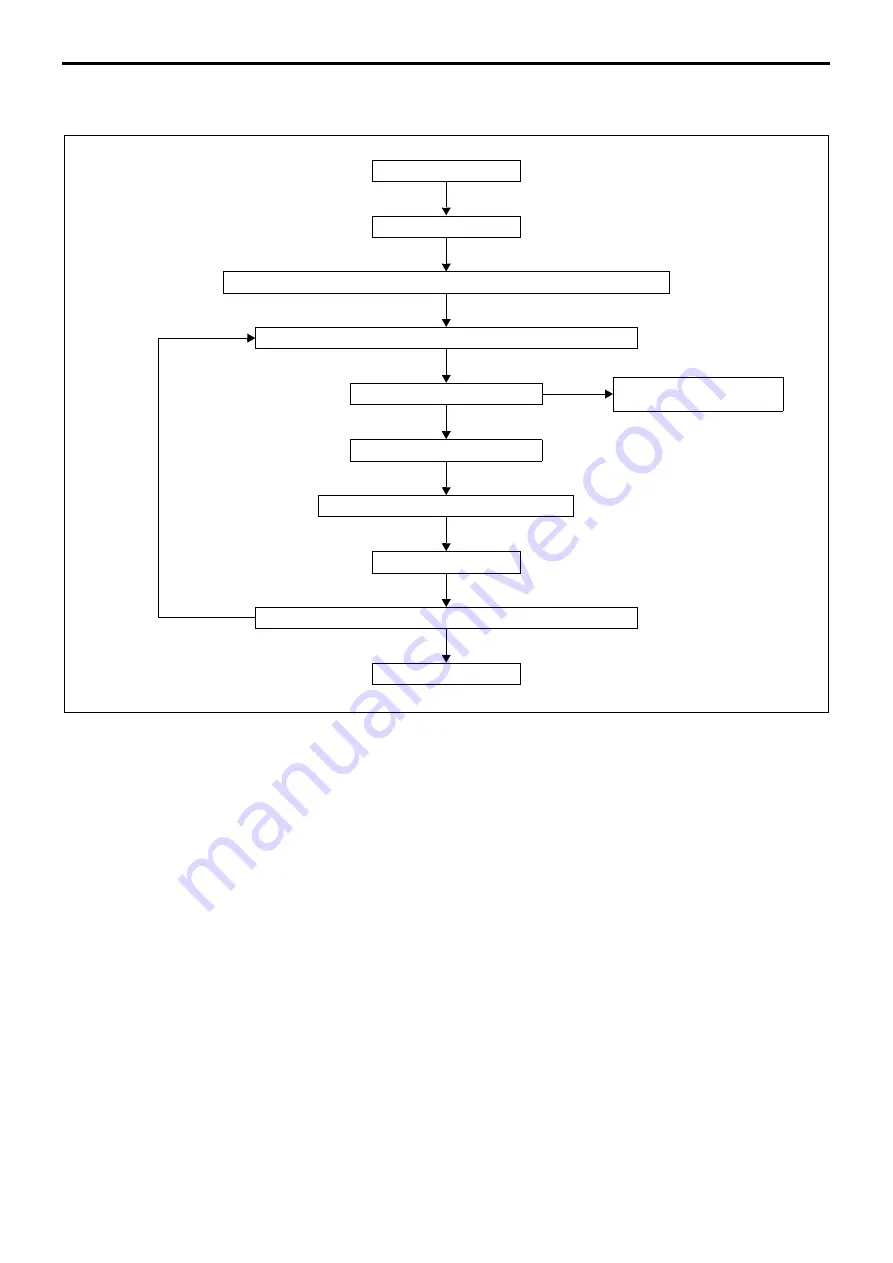
1. Diagnosis Procedure
•
Perform the inspection in accordance with the following flowchart.
2. Diagnostic Precautions
•
Before measuring voltage, check the battery for charged condition and specific gravity. If system inspection is per-
formed with the battery uncharged or reduced in specific gravity, accurate measurements cannot be achieved.
•
Before disconnecting battery cables, harnesses and connectors, set the starter switch to LOCK or OFF, then allow
at least 20 seconds.
•
To avoid having electrical parts damaged, set the starter switch and lighting switch to LOCK or OFF before recon-
necting battery cables, harnesses and connectors.
•
When performing measurement with the tester, handle the test bar carefully so that it does not damage internal
circuit and other electrical parts of the electronic control unit to result in a short-circuit failure between terminals in
connector or between connector and car body.
•
Resistance is affected by temperature. Determine the necessity of resistance measurement following given tem-
perature specification as a guide. Otherwise, use normal temperature (10 to 35
°
C) as the measuring condition.
Vehicle in service shop
Read all (past and present) diagnosis codes by Multi-Use Tester. (See Gr00.)
Warning lamp lit
Was able to identify the fault?
Response to transient fault
(See Gr00.)
Perform inspection based on diagnosis codes. (See later section.)
Rectify or replace with new parts.
Clear stored diagnosis code. (See Gr00.)
Read diagnosis code(s) by Multi-Use Tester. (See Gr00.)
Code issued
End of inspection
Test drive
NO
YES
No code issued
EXHAUST GAS RECIRCULATION SYSTEM
Содержание 6M70
Страница 29: ...M E M O 11 19 11 ...
Страница 35: ...M E M O 11 25 11 ...
Страница 36: ...11 26 MITSUBISHI 6M70 ROCKER COVER ROCKER AND SHAFT ...
Страница 40: ...11 30 MITSUBISHI 6M70 CAMSHAFT AND ROCKER CASE ...
Страница 47: ...M E M O 11 37 11 ...
Страница 48: ...11 38 MITSUBISHI 6M70 CYLINDER HEAD AND VALVE MECHANISM ...
Страница 63: ...M E M O 11 53 11 ...
Страница 71: ...M E M O 11 61 11 ...
Страница 77: ...M E M O 11 67 11 ...
Страница 81: ...M E M O 11 71 11 ...
Страница 98: ...11 88 MITSUBISHI 6M70 CRANKSHAFT AND CRANKCASE ...
Страница 127: ...M E M O 12 21 12 ...
Страница 129: ...M E M O 12 23 12 ...
Страница 135: ...M E M O 13 3 13 ...
Страница 138: ...13 6 1 1 Mitsubishi 6M70 Supply pump STRUCTURE AND OPERATION ...
Страница 150: ...13 18 10 Electronic control unit connection diagram STRUCTURE AND OPERATION ...
Страница 151: ...13 13 19 ...
Страница 155: ...M E M O 13 23 13 ...
Страница 185: ...M E M O 13 53 13 ...
Страница 189: ...M E M O 13 57 13 ...
Страница 205: ...M E M O 13 73 13 ...
Страница 211: ...M E M O 13 79 13 ...
Страница 215: ...M E M O 13 83 13 ...
Страница 219: ...M E M O 13 87 13 ...
Страница 225: ...M E M O 13 93 13 ...
Страница 226: ...13 94 INSTALLED LOCATIONS OF PARTS ...
Страница 227: ...13 13 95 ...
Страница 228: ...13 96 INSTALLED LOCATIONS OF PARTS ...
Страница 229: ...13 13 97 ...
Страница 230: ...13 98 INSTALLED LOCATIONS OF PARTS ...
Страница 231: ...13 13 99 ...
Страница 232: ...13 100 MITSUBISHI 6M70 INSTALLED LOCATIONS OF PARTS ...
Страница 233: ...13 13 101 ...
Страница 234: ...13 102 ELECTRIC CIRCUIT DIAGRAM ...
Страница 235: ...13 13 103 ...
Страница 236: ...13 104 ELECTRIC CIRCUIT DIAGRAM ...
Страница 237: ...13 13 105 ...
Страница 238: ...13 106 ELECTRIC CIRCUIT DIAGRAM ...
Страница 241: ...14 14 3 1 Mitsubishi 6M70 Cooling System Flow of Coolant STRUCTURE AND OPERATION ...
Страница 252: ...14 14 Periphery of Engine DISCONNECTION AND CONNECTION OF HOSES AND PIPES ...
Страница 271: ...M E M O 14 33 14 ...
Страница 286: ...M E M O 15 13 15 ...
Страница 295: ...15 22 7 Installed Locations of Parts TURBOCHARGER CONTROL SYSTEM ...
Страница 296: ...15 15 23 ...
Страница 297: ...15 24 TURBOCHARGER CONTROL SYSTEM ...
Страница 298: ...15 15 25 ...
Страница 299: ...15 26 TURBOCHARGER CONTROL SYSTEM ...
Страница 300: ...15 15 27 ...
Страница 301: ...15 28 TURBOCHARGER CONTROL SYSTEM ...
Страница 302: ...M E M O 15 29 15 ...
Страница 303: ...15 30 8 Electric Circuit Diagram TURBOCHARGER CONTROL SYSTEM ...
Страница 304: ...15 15 31 ...
Страница 305: ...15 32 TURBOCHARGER CONTROL SYSTEM ...
Страница 306: ...M E M O 15 33 15 ...
Страница 330: ...M E M O 15 57 15 ...
Страница 340: ...17 6 1 3 Electronic control unit connection diagram STRUCTURE AND OPERATION ...
Страница 343: ...M E M O 17 9 17 ...
Страница 351: ...M E M O 17 17 17 ...
Страница 352: ...17 18 8 Installed Locations of Parts EXHAUST GAS RECIRCULATION SYSTEM ...
Страница 353: ...17 17 19 ...
Страница 354: ...17 20 EXHAUST GAS RECIRCULATION SYSTEM ...
Страница 355: ...17 17 21 ...
Страница 356: ...17 22 EXHAUST GAS RECIRCULATION SYSTEM ...
Страница 357: ...17 17 23 ...
Страница 358: ...17 24 9 Electric Circuit Diagram EXHAUST GAS RECIRCULATION SYSTEM ...
Страница 359: ...17 17 25 ...
Страница 360: ...17 26 MITSUBISHI 6M70 EGR VALVE EGR MAGNETIC VALVE EGR PIPE AND EGR COOLER ...


