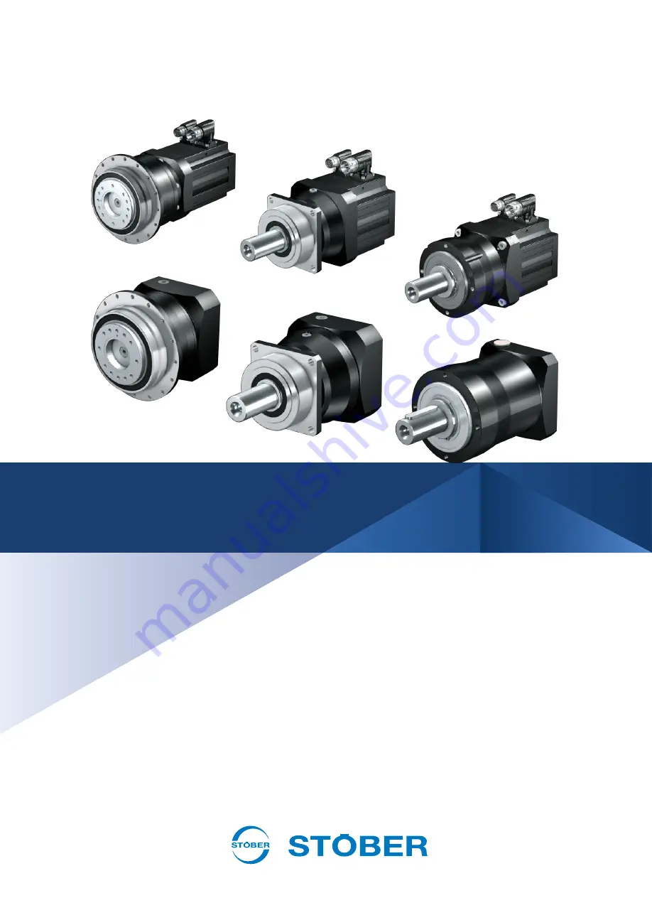
P/PE/PH/PHQ/PHV gear units, geared motors Operating manual
en-US10/2019 ID 443149_en.00
Страница 1: ...P PE PH PHQ PHV gear units geared motors Operating manual en US 10 2019 ID 443149_en 00 ...
Страница 2: ...nical hazards 6 2 3 2 Thermal hazards 7 2 4 Prevention of property damage 7 3 Product description 8 3 1 Basic structure of P PE 8 3 2 Basic structure of PH PHQ PHV 9 3 3 PE type designation 9 3 4 P2 P9 PH3 PH8 PHQ4 PHQ8 type designation 10 3 5 PH9 PH10 PHQ9 PHQ12 PHV9 PHV10 type designation 11 3 6 Nameplate 11 3 7 Mounting positions 12 3 8 Direction of rotation 12 3 9 Reverse operation 13 3 10 Amb...
Страница 3: ...tor on a gear unit with MB adapter 23 5 3 Mounting drive elements on a solid shaft 23 5 4 Mounting drive elements on a flange shaft 24 5 5 Mounting the gear unit on the machine 26 5 6 Tightening torques 28 6 Commissioning 29 6 1 Before commissioning 29 6 2 During commissioning 29 7 Servicing 30 7 1 Cleaning 30 7 2 Inspection 30 7 3 Remedying faults 31 7 3 1 Troubleshooting faults 31 7 4 Servicing ...
Страница 4: ...signal words are used to emphasize specific information so that you are able identify it in this documentation quickly Safety notes indicate special risks when handling the product and are accompanied by relevant signal words that express the extent of the risk In addition warning notes for possible property damage and useful information are also indicated by signal words DANGER Danger This word w...
Страница 5: ... serial number of the gear unit at https id stober com or by scanning the QR code on the nameplate of the gear unit Alternatively you can find supporting documents at http www stoeber de en downloads Enter the ID of the documentation in the Search field Drive components Operating manual ID LM Lean motor 443048_en EZ synchronous servo motor 443032_en MB motor adapter with brake 441846_en 1 6 Limita...
Страница 6: ...hibited unless they are expressly designed for this 2 2 Requirements for personnel All mechanical tasks that arise during the assembly commissioning maintenance and removal of the product may be performed only by specialized personnel who hold a corresponding qualification in the field of metal technology All electrical tasks that arise during the assembly commissioning maintenance and removal of ...
Страница 7: ...e provided drive elements properly or remove them before a test run 2 3 2 Thermal hazards CAUTION The surface of the drive can reach temperatures over 65 C during operation Touching the hot surface of the drive can cause severe skin burns Do not touch the drive during operation or immediately afterward Allow the drive to cool sufficiently before carrying out work on the drive Wear protective glove...
Страница 8: ...e order confirmation You will find more product information and dimensional drawings in the corresponding catalog Additional documentation 15 The respective separate technical documentation applies to the attached motors 3 1 Basic structure of P PE Tab 1 Basic structure of a P532 two stage gear unit left and PE411 single stage gear unit right 1 Solid shaft 2 Feather key if present 3 Output flange ...
Страница 9: ...ation of the type designation for the gear unit types mentioned in the title Sample code PE 4 1 2 S G R 0200 ME Explanation Code Designation Design PE Type Planetary gear unit 4 Size 4 example 1 Generation Generation 1 1 2 Stages Single stage Two stage S Housing Standard G P Shaft Solid shaft without feather key Solid shaft with feather key R Bearing Standard bearing 0200 Transmission ratio i x 10...
Страница 10: ... Three stage S Housing Standard F G P Shaft Flange shaft PH PHQ gear unit Solid shaft without feather key P gear unit Solid shaft with feather key P gear unit S D Z V Bearing Standard bearing Axially reinforced bearing P gear unit Radially reinforced bearing P gear unit Reinforced bearing PH PHQ gear unit S R Backlash Standard Reduced 0100 Transmission ratio i x 10 i 10 example ME MEL MF MFL MB Mo...
Страница 11: ...o i x 10 i 20 example ME MEL MF MFL MB Motor adapter Motor adapter with EasyAdapt coupling Motor adapter with EasyAdapt coupling for large motors Motor adapter with FlexiAdapt coupling Motor adapter with FlexiAdapt coupling for large motors ServoStop motor adapter with brake EZ LM Motor EZ synchronous servo motor LM Lean motor 3 6 Nameplate An example gear unit nameplate is explained in the figure...
Страница 12: ...PHQ three stage planetary gear units for which the lubricant fill volume depends on the mounting position These planetary gear units must be installed in the mounting position that was specified in the order EL1 EL5 EL6 Horizontal output Vertical downward output Vertical upward output Tab 3 Mounting positions of a PHQ three stage planetary gear unit 3 8 Direction of rotation The input and output s...
Страница 13: ...unimportant when installing the machine In horizontal mounting positions the output shaft for P PH PHQ PHV planetary gear units must be oriented as follows when installing the machine The marks or the position of the feather key indicate the center position of reverse operation Fig 2 Orientation of the feather key 1 during reverse operation of P planetary gear units with solid shaft and feather ke...
Страница 14: ...ith harmful oils acids gases vapors dust or radiation Extreme temperature fluctuations with high humidity Thawing or icing Strong UV radiation e g direct sunlight Presence of salt spray Sparks In potentially explosive atmospheres only gear units in an explosion proof design in accordance with ATEX Directive 2014 34 EU may be used Separate documentation applies to the explosion proof design 3 11 Ot...
Страница 15: ...oduct combination Catalog title ID Gear unit MB motor adapter with brake Motor adapters with brake 441904 Gear unit ME MEL MF MFL motor adapter Servo gear units 443054_en Gear unit EZ synchronous servo motor EZ synchronous servo geared motors 442437_en Gear unit LM Lean motor Lean motors 443016_en If you have questions about your drive that are not answered by this documentation please contact STO...
Страница 16: ... may require lifting gear e g a crane depending on the weight The weight of your drive is specified in the accompanying delivery documents Lift and transport the drive as follows Use lifting gear with a sufficient lifting capacity for the weight of the drive Run hoist slings directly around the drive housing and secure the hoist slings from slipping In order to prevent the drive from falling or ge...
Страница 17: ...t weaken the sealing lips of the shaft seal rings Otherwise you can use commercially available solvents Be aware that all surfaces that come into contact with each other in a clamp connection must be degreased with a cold cleaner or solvent for error free torque transmission Additional information can be found in the following chapters ATTENTION Shaft seal rings can be damaged by solvents Prevent ...
Страница 18: ...bly on a STOBER gear unit with motor adapter Dimensional drawings of the motor adapter can be found in the corresponding catalog Additional documentation 15 Tolerances for shafts in accordance with DIN 748 1 Diameter mm Tolerance 50 ISO k6 50 ISO m6 Tolerances for centering diameter on the motor flange in accordance with EN 50347 Centering diameter mm Flange size mm Tolerance 230 65 300 ISO j6 230...
Страница 19: ...or shaft STOBER recommends mounting the motor on the gear unit with the motor shaft pointing down vertically 1 Position the gear unit 5 if necessary with the aid of lifting gear on a suitable support 1 so that the motor can be mounted in a vertical position Make sure that the weight of the gear unit is not supported on the output shaft 2 Remove the transport cover of the motor adapter 3 If a feath...
Страница 20: ...xagon insert 3 in this process the clamping hub widens because the cross pin 12 locks against the cylinder head of the locking screw The size of the hexagon insert can be found on the adhesive label 14 as well as in the following tables 15 If necessary repeat the previous step 16 The contact surfaces of the motor flange and motor adapter flange must fit together without a gap If this is not the ca...
Страница 21: ...nit with ME motor adapter example 1 Support 2 Torque wrench 3 Hexagon insert 4 Motor adapter 5 Planetary gear unit 6 Clamping sleeve if present 7 Motor shaft 8 Motor 9 Screw 10 Slot of the clamping hub 11 Locking screw 12 Cross pin 13 Threaded sealing plug 14 Adhesive label 15 Clamping hub ...
Страница 22: ...30 P931 M16 14 310 P932 M12 10 130 M16 14 310 PH331 M5 4 9 0 M6 5 16 PH431 M6 5 16 M8 6 40 PH432 M5 4 9 0 M6 5 16 PH531 M8 6 40 M10 8 75 PH532 M6 5 16 M8 6 40 PH731 M10 8 75 M12 10 130 PH732 M8 6 40 M10 8 75 PH831 M12 10 130 M16 14 310 PH832 M10 8 75 M12 10 130 PH932 M12 10 130 M16 14 310 PH1032 M12 10 130 M16 14 310 PHQ431 M6 5 16 M8 6 40 PHQ432 M5 4 9 0 M6 5 16 PHQ531 M8 6 40 M10 8 75 PHQ532 M6 ...
Страница 23: ... 40 PE511 M8 6 40 M10 8 75 PE512 M8 6 40 M10 8 75 Abbreviations used KS Nominal diameter of the locking screw 11 MA Tightening torque for the locking screw 11 s Size of the hexagon insert 3 5 2 4 Mounting the motor on a gear unit with MB adapter The assembly of a motor on a gear unit with an MB motor adapter with brake is described in a separate document see Supporting documents 5 5 3 Mounting dri...
Страница 24: ...aning agent and solvent 17 is observed A mounting device suitable for the drive element is available not included in the scope of delivery Procedure 1 Remove the corrosion protection from the solid shaft 2 Degrease the inner hole of the drive element 3 Mount the drive element on the solid shaft with the aid of a mounting device positioned on the centering hole of the solid shaft Details can be fou...
Страница 25: ...ge shaft and drive element 2 Center the drive element over the inner or outer pilot of the flange shaft The inner pilot has a fit of ISO H6 and the outer pilot of ISO h7 see the figure in the chapter Mounting the gear unit on the machine 26 3 Mount the drive element on the flange shaft with screws of strength class 12 9 Further details on the screws can be found in the following table 4 Tighten th...
Страница 26: ...ed drive is ensured Procedure 1 Position the gear unit so that the nameplate of the gear unit is still visible after mounting 2 If the gear unit is to be operated in reverse operation make sure that the output shaft is positioned according to the specifications in the chapter Reverse operation 13 3 Center the gear unit in the connecting structure using the pilot pilots of the gear unit housing 4 M...
Страница 27: ... flange shaft 6 Threaded hole for disassembly if present Gear unit type Number of screws Screw size Min screw in depth mm Strength class P2 4 M5 12 9 P3 4 M5 12 9 P4 4 M6 12 9 P5 4 M8 12 9 P7 4 M10 12 9 P8 4 M12 12 9 P9 4 M16 12 9 PE2 4 M4 8 10 9 PE3 4 M5 10 10 9 PE4 4 M6 13 10 9 PE5 4 M8 16 10 9 PH3 8 M4 12 9 PH4 16 M5 12 9 PH5 16 M5 12 9 PH7 24 M6 12 9 PH8 24 M8 12 9 PH9 PHV9 32 M12 12 9 PH10 PH...
Страница 28: ... machine For clamp couplings clamping screws of shrink rings and other connection elements other tightening torques apply that are specified in the specific context Tightening torque MA Nm Thread Strength class 8 8 Strength class 10 9 Strength class 12 9 M4 3 3 4 8 5 6 M5 6 5 9 5 11 2 M6 11 3 16 5 19 3 M8 27 3 40 1 46 9 M10 54 79 93 M12 93 137 160 M14 148 218 255 M16 230 338 395 M18 329 469 549 M2...
Страница 29: ...ation while plug connectors are being disconnected electric arcs can cause severe injury or even death Do not connect or disconnect the plug connectors until after the motor is de energized WARNING Flying metal parts can cause serious injuries Assemble the provided power transmission elements properly or remove the feather key before a test run CAUTION The surface of the drive can reach temperatur...
Страница 30: ... entering the interior of the gear unit geared motor through the seals and can damage it In addition do not use solvents as these can damage the seals and the nameplate Comply with the following instructions Remove dust and chips with a suitable industrial vacuum Remove contamination from the surface of the gear unit geared motor with a suitable industrial cleaner 7 2 Inspection Perform regular in...
Страница 31: ... the motor Replace the motor Surrounding temperature is too high Provide sufficient cooling for the gear unit Bearing damage Contact STOBER Service Increased or different noises or vibrations in operation Motor is mounted with too much tension Check the assembly of the motor Gear unit is mounted incorrectly or with too much tension Check the assembly of the gear unit Bearing damage Contact STOBER ...
Страница 32: ...nces Presumed cause If possible digital photo of the drive or a video recording of the drive in the context of the fault Contact data of parent company in Germany STÖBER Antriebstechnik GmbH Co KG Kieselbronner Strasse 12 75177 Pforzheim Germany Service hotline 49 7231 582 3000 mail stoeber de Contact data of subsidiary in US STOBER Drives Inc 1781 Downing Drive Maysville KY 41056 Service Hotline ...
Страница 33: ...ding conductor from the motor 3 If necessary remove drive elements connected to the output shaft such as belts chains or couplings with suitable removal devices 4 Fasten the drive with suitable fastening elements see the chapter Transport 16 5 Unscrew the screws used to mount the drive to the machine 6 Pull the output flange of the gear unit off of the machine For gear units with a flange shaft us...
Страница 34: ...STÖBER Antriebstechnik GmbH Co KG Kieselbronner Str 12 75177 Pforzheim Germany Tel 49 7231 582 0 mail stoeber de www stober com 443149_en 00 10 2019 24 h Service Hotline 49 7231 582 3000 www stober com ...