background image


2 Unpacking to Installation

   Confirming the operation

   2-25

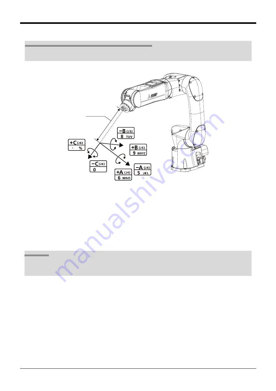
Changing the flange surface posture

* The control point does not change.

• When the[+A (J4)] keys is pressed, the X axis will rotate in the plus direction of the tool coordinate sys-

tem.
When the[-A (J4)] keys is pressed, rotate in the minus direction.

• When the[+B (J5)] keys is pressed, the Y axis will rotate in the plus direction of the tool coordinate sys-

tem.
When the[-B (J5)] keys is pressed, rotate in the minus direction.

• When the[+C (J6)] keys is pressed, the Z axis will rotate in the plus direction of the tool coordinate sys-

tem.
When the[-C (J6)] keys is pressed, rotate in the minus direction.

If the buzzer of T/B sounds and the robot does not move

If it is going to move the robot across the operation range, the buzzer of T/B sounds and the robot does not 
move. In this case, please move to the counter direction.

+

X

+

Y

+

Z

SPACE

,

+

-

+

-

+

-

Tool length

Tool length

The default tool length is 0mm, and the control point is the center of the end axis.
After installing the hand, set the correct tool length in the parameters. Refer to the separate manual "Detailed 
Explanation of Functions and Operations" for details.

Содержание melfa RV-5AS

Страница 1: ...Mitsubishi Electric Industrial Robot RV 5AS InstructionManual Robot Arm Setup and Maintenance BFP A3729 A ...

Страница 2: ......

Страница 3: ...grators must select and use functions correctly Peripherals must be designed manufactured set programmed maintained and inspected appropriately Before working with collaborative robots conduct risk assessments check that no risk is present and ensure all required documentation is in order It is vitally important that all the points mentioned above are fully understood in order to work with collabo...

Страница 4: ...Revision history Date of Print Instruction Manual No Revision Details 2020 04 10 BFP A3729 First print 2020 07 30 BFP A3729 A Revised the guidelines for unpacking the robot ...

Страница 5: ...ollowing robot type Robot type RV 5AS No part of this manual may be reproduced by any means or in any form without prior consent from Mitsubishi The details of this manual are subject to change without notice The information contained in this document has been written to be accurate as much as possible Please interpret that items not described in this document cannot be performed or alarm may occu...

Страница 6: ...g the operation 2 14 2 3 1 Installing the teaching pendant T B 2 15 2 3 2 Turning ON the control power 2 15 2 3 3 Preparing the T B 2 16 1 JOINT jog operation 2 20 2 XYZ jog operation 2 22 3 TOOL jog operation 2 24 4 3 axis XYZ jog operation 2 26 5 CYLNDER jog operation 2 28 6 Work jog operation 2 30 2 3 4 Setting the hand parameters 2 37 3 Installing the option devices 3 38 3 1 Installing the sol...

Страница 7: ...e This manual Describes the procedures unpacking transport installation and operation check maintenance and inspection to use the robot arm BFP A3729 Controller Setup and Maintenance Describes the procedures unpacking transport and installation maintenance and inspection to use the robot controller BFP A3731 Collaborative Robot Detailed explanations of functions and operations Describes functions ...

Страница 8: ...ution indicating cases where the operator could be subject to fatalities or serious injuries if handling is mistaken Always observe these precautions to safely use the robot Precaution indicating cases where operator could be subject to injury or physical damage could occur if handling is mistaken Always observe these precautions to safely use the robot JOG Square brackets are used to represent op...

Страница 9: ...y before using this product Take precautions as necessary 2 2 1 Unpacking The robot is shipped from the factory in cardboard packing For details on transportation of the robot arm refer to 2 2 2 Transportation procedure with two people Always unpack the robot at a flat place The robot could tilt over if unpacked at an unstable place 1 Cut the banding straps with scissors and open the box No Part n...

Страница 10: ...2 4 Installation 2 Unpacking to Installation 2 Pull the box up and remove it 3 Remove the left and right inserts 4 Remove the top inserts Box Inserts Inserts ...

Страница 11: ...hold the end of the forearm and elbow while another person holds the area under the elbow Mass 32kg Place the robot on a flat surface Fix the robot in place or have somebody support it during installation External forces may cause the robot to fall if the robot is not fixed in place or supported during installation Plastic bag Elbow End of the forearm CAUTION ...

Страница 12: ...to Installation 7 Remove the support bracket for the mechanical interface once the robot has been installed The support bracket and packaging are required when relocating the robot Keep them in a safe place Support bracket CAUTION ...

Страница 13: ... cover may become damaged Do not apply force to the cover or subject the robot to large impacts during trans portation Ensure that the machine cable does not get caught on anything or get pulled during trans portation 3 Transfer the robot slowly Be careful not to get injured with the edge of the robot arm 4 Before moving the robot to a new location re attach the support bracket to the mechanical i...

Страница 14: ...by 6 3 Ra or more If the installation surface is rough the contact with the table will be poor and positional deviation could occur when the robot moves 4 When installing use a common table to prevent the position of the devices and jigs subject to robot work from deviating 5 The installation surface must have sufficient strength to withstand the arm reaction during operation and resistance agains...

Страница 15: ... Ceiling mounting procedure 1 Use three people to assist with the installation of the robot when mounting it to a ceiling Transport the robot to a position beneath the installation area Refer to 2 2 2 Transportation procedure with two people before moving the robot to this position 2 Insert the forks of a forklift into a pallet then place the robot on the pallet To protect the acrylic cover set th...

Страница 16: ...rd person lift the pallet up with the forklift so that the base of the robot comes into contact with the installation area 5 There are four installation holes φ9 on the base of the robot Secure the robot into place using these holes with the included parts below Recommended tightening torque 26 5 N m Installation screws M8 hex socket screws Spring washers for installation screws Plain washers for ...

Страница 17: ...grounding point should be as close to the robot arm and controller as possible and the length of the grounding wire should be short Fig 2 3 Grounding methods 2 Grounding procedures 1 Prepare the grounding cable AWG 11 4 2mm2 or more and robot side installation screw and washer 2 If there is rust or paint on the grounding screw section A remove it with a file etc 3 Connect the grounding cable to th...

Страница 18: ...rted connector close the latches of the CN1 connector 4 The connection method is the same for the optional machine cables replaceable type When connecting and disconnecting the connector be careful not to get your hand pinched When installing or removing the connector to the connector of the other party in parallel install or remove If load strong against one side is applied the connector pin may ...

Страница 19: ...pecial care to the leading of the connection cable If the cable is pulled with force or bent excessively wires could break or the connector could be damaged Connect the machine cable at the place without the effect of the dust or oil mist CAUTION CAUTION ...

Страница 20: ...ck of the T B Note The figure of the robot which indicated to the explanation page in each jog mode is an example The robot will move during this operation Make sure that there are no operators near the robot and that there are no obstacles such as tools in the robot oper ation range To immediately stop the robot release the deadman switch on the back of the T B The servo power will turn OFF and t...

Страница 21: ...at the controller s power supply is OFF 2 Refer to Fig 2 7 and connect T B connector to the robot controller Use as the upper surface the lock lever and push in until there is sound 3 Pressing down the lock lever to lock the connector as shown below Fig 2 7 Installing the T B 2 3 2 Turning ON the control power Confirm that there are no operators near the robot before turning the power ON 1 Turn th...

Страница 22: ...op related operations such as an emergency stop can be performed regardless of the valid invalid setting How to choose the jog mode Press the JOG key the jog screen will be dis played and display the jog mode which can be chosen at the bottom of the screen Because these correspond to the function key of F1 F4 press the function key corresponding to the jog mode to wish And if the FUNCTION key is p...

Страница 23: ...peration The axis moves straight along the XYZ coordinate system The flange surface posture is maintained Also while maintaining the flange surface position the flange surface posture changes Fig 2 9 XYZ jog operation J3 axis J2 axis J1 axis J6 axis J5 axis J4 axis X X Y Y Z Z X Y Z Control point Tool length ...

Страница 24: ...on the flange surface posture changes Fig 2 10 TOOL jog operation The axis moves straight along the base coordinate system At this time the flange surface posture is not maintained Also the flange surface posture changes The flange surface position does not change at this time Fig 2 11 3 axis XYZ jog operation X Y Y Z X Z Control point Tool length X X Y Y Z Z Tool length J5 axis J6 axis J4 axis Co...

Страница 25: ...system While maintaining the flange surface posture the axis moves straight along the work coordinate sys tem Also while maintaining the flange surface position the flange surface posture changes Jog operation around the work coordinate system is available Ex T jog In this jog operation when the jog operation is performed for the posture elements the posture rotates on the Xw axis Yw axis or Zw ax...

Страница 26: ... setting speed is displayed on screen upper right Set the override to 10 here for confirmation work J1 axis jog operation When the X J1 keys is pressed the J1 axis will rotate in the plus direction When the X J1 keys is pressed rotate in the minus direction J2 axis jog operation When the Y J2 keys is pressed the J2 axis will rotate in the plus direction When the Y J2 keys is pressed rotate in the ...

Страница 27: ...tate in the minus direction When the B J5 keys is pressed the J5 axis will rotate in the plus direction When the B J5 keys is pressed rotate in the minus direction When the C J6 keys is pressed the J6 axis will rotate in the plus direction When the C J6 keys is pressed rotate in the minus direction J3 axis SPACE J5 axis J6 axis J4 axis If the buzzer of T B sounds and the robot does not move If it ...

Страница 28: ... robot will move along the X axis plus direction When the X J1 keys is pressed move along the minus direction When the Y J2 keys is pressed the robot will move along the Y axis plus direction When the Y J2 keys is pressed move along the minus direction When the Z J3 keys is pressed the robot will move along the Z axis plus direction When the Z J3 keys is pressed move along the minus direction to S...

Страница 29: ...essed the axis will rotate around the Z axis in the plus direction When the C J6 keys is pressed rotate in the minus direction If the buzzer of T B sounds and the robot does not move If it is going to move the robot across the operation range the buzzer of T B sounds and the robot does not move In this case please move to the counter direction X X Y Y Z Z X Y Z SPACE Control point Tool length Tool...

Страница 30: ...ordi nate system When the X J1 keys is pressed the axis will move along the minus direction When the Y J2 key is pressed the axis will move along the Y axis plus direction of the tool coordi nate system When the Y J2 key is pressed the axis will move along the minus direction When the Z J3 keys is pressed the axis will move along the Z axis plus direction of the tool coordi nate system When the Z ...

Страница 31: ...en the C J6 keys is pressed the Z axis will rotate in the plus direction of the tool coordinate sys tem When the C J6 keys is pressed rotate in the minus direction If the buzzer of T B sounds and the robot does not move If it is going to move the robot across the operation range the buzzer of T B sounds and the robot does not move In this case please move to the counter direction X Y Z SPACE Tool ...

Страница 32: ...e When the X J1 keys is pressed the robot will move along the X axis plus direction When the X J1 keys is pressed move along the minus direction When the Y J2 keys is pressed the robot will move along the Y axis plus direction When the Y J2 keys is pressed move along the minus direction When the Z J3 keys is pressed the robot will move along the Z axis plus direction When the Z J3 keys is pressed ...

Страница 33: ...xcept J5 and J6 When the A J4 key is pressed the axis will rotate in the minus direction When the B J5 keys is pressed the J5 axis will rotate in the plus direction At this time to maintain the flange s position other axes move simultaneously except J4 and J6 When the B J5 keys is pressed the axis will rotate in the minus direction When the C J6 keys is pressed the J6 axis will rotate in the plus ...

Страница 34: ... arc centering on the Z axis The direction of the frange will not change Assuming that the current position is on an arc centering on the Z axis the robot moves along that arc When the X J1 keys is pressed the robot will expand in the radial direction When the X J1 keys is pressed contract in the radial direction When the Y J2 keys is pressed the robot will move along the arc in the plus direction...

Страница 35: ...d the X axis in the plus direction When the A J4 keys is pressed rotate in the minus direction When the B J5 key is pressed the axis will rotate around the Y axis in the plus direction When the B J5 keys is pressed rotate in the minus direction When the C J6 key is pressed the axis will rotate around the Z axis in the plus direction When the C J6 keys is pressed rotate in the minus direction X X Y...

Страница 36: ...h the coordinate value of A B and C axis is not used positioning will get easy if the XYZ jog or TOOL jog movement is effected with the same value The direc tion of the hand is the same Fig 2 14 Setting of the work coordinates system teaching point The setting definition method of the work coordinates system is shown in the following 1 Select 6 ENHANCED screen on the MENU screen 2 Press the 2 keys...

Страница 37: ...d if the CLOSE key is pressed Teach the three points WO WX and WY by the same operation The position data taught here is each registered into the following parameters n means the work coor dinates numbers 1 8 WO parameter WKnWO WX parameter WKnWX WY parameter WKnWY WORK COORD WORK NUMBER 1 TEACHING POINT WO X 0 00 Y 0 00 Z 0 00 123 W JUMP W GRID CLOSE WORK JUMP CHOOSE ONE OF THE WORK NUMBER 1 8 12...

Страница 38: ... the MENU screen Although setting of work coordinates is finishing above confirmation of work coordinates can be done by pressing the function key corresponding to W GRID F2 Then the operation method of the work jog is shown Change to the work jog after nearing the work WORK COORD WORK NUMBER 2 TEACHING POINT WO X 214 12 Y 61 23 Z 553 30 123 TEACH WX WY DEFINE WORK COORD WORK NUMBER 2 WORK COORDIN...

Страница 39: ...Conversely if the OVRD Lower arrow key is pressed it will go down The current setting speed is displayed on screen upper right Set the override to 10 here for confirmation work The WORK jog operation and the Ex T jog operation can be switched by setting the parameters WK1 JOGMD to WK8JOGMD of each work coordinates system The respective operations are as follows WORK jog operation mode Conventional...

Страница 40: ...eys is pressed Move along the minus direction When the Y J2 keys is pressed the robot will move along the Y axis Yw plus direction on the work coordinates system When the Y J2 keys is pressed Move along the minus direction When the Z J3 keys is pressed the robot will move along the Z axis Zw plus direction on the work coordinates system When the Z J3 keys is pressed Move along the minus direction ...

Страница 41: ...te around the X axis in the plus direction When the A J4 keys is pressed rotate in the minus direction When the B J5 key is pressed the axis will rotate around the Y axis in the plus direction When the B J5 keys is pressed rotate in the minus direction When the C J6 key is pressed the axis will rotate around the Z axis in the plus direction When the C J6 keys is pressed rotate in the minus directi...

Страница 42: ... in the minus direction When the C J6 keys is pressed the control point will rotate in the plus direction around the Z axis Zw of work coordinates system Ex T coordinates system When the C J6 keys is pressed the control point will rotate in the minus direction Xw Yw Zw Zw Xw Yw Xw Yw Zw Zw Xw Yw Xw Yw Zw Zw Xw Yw X Y Z Z X Y X Y Z Z X Y X Y Z Z X Y Work coordinates system Ex T coordinates system C...

Страница 43: ...the sink type or the source type for the sole noid valve and the logic of the hand input signal 1 Not set 0 Source type 1 Sink type 1 Hand condition HNDDAT is 0 to 8 Set the initial condition of the hand Specify with the tool coordinate system Weight size X size Y size Z center of gravity X cen ter of gravity Y center of gravity Z Unit Kg mm The setting varies depending on the model Tool length Th...

Страница 44: ...before attempting these steps 1 Remove the M4 truss screws attaching the base cover to the back of the robot four places then gen tly remove the base cover It may be difficult to remove the cover depending on the posture of the robot Use Jog operation to move the robot into a posture that makes removal of the cover easier 2 Pull out the GR connector and the φ4 air hoses so that they stick out past...

Страница 45: ...ir to pressurize the robot For further information on using the robot in oil mist environments refer to the section Protection specifications in the Standard Specifications Manual 4 Use the provided M4 30 screws 2 pcs to secure the solenoid valve set to the bracket on robot 5 Connect the robot s φ4 air hoses 4 to the A and B ports on the solenoid valve set Table 3 1 shows how tools can be connecte...

Страница 46: ...ector to the solenoid valve GR1 connector After connecting the connectors locate them in the connector space indicated in the image below Do not cut the cable tie that holds the cables together in the wiring space Hand Hand condition Solenoid valve port No Φ4 air hose No Solenoid valve set in use Hand 1 Open A port 1 1 One set Close B port 2 2 Hand 2 Open A port 3 3 Two sets Close B port 4 4 A por...

Страница 47: ...talling the cover Insert the gasket into the groove The robot will not meet protection specifications if the gasket is not in place Power on the robot controller Then select the solenoid valve type sink source and set the parameters HIOTYPE and HANDTYPE to match the output signals the hand is connected to For further information on setting parameters refer to the section Parameter Settings in the ...

Страница 48: ...ion and maintenance works Table 4 1 Type of inspection and maintenance works No Type of inspection and maintenance works Description Operating time Note1 Note1 The operating hours assume the robot operation of 15 hours per day for 20 days per month When the robot operates for 8 hours per day the operating hours per month become about a half of the one under the above condition Then the monthly ins...

Страница 49: ...ystem Are there any air leaks drain clogging or hose damage Is the air source nor mal Visual Drain the drainage and remedy the air leaks replace the part After turning the power ON Turn the power ON while monitoring the robot 1 Is there any abnormal motion or abnormal noise when the power is turned ON Follow the troubleshooting section 2 Check that the robot becomes in the servo off state by the S...

Страница 50: ...Inspection item Carry out periodic inspection given in Table 4 3 Table 4 3 Periodic inspection items details Inspection item details Remedies Monthly inspection Are any of the bolts or screws on the robot arm loose Securely tighten the bolts Are any of the connector fixing screws or terminal block terminal screws loose Securely tighten the screws ...

Страница 51: ...ours when the robot operates 8 hours per day for 20 days per month for three months 8 hr day 20 days month 3 months 480hr Approx 500 hr Inspection schedule Type of periodic inspection works Note2 Note2 The item marked with the circle is to be performed According to the guideline of the operat ing hours perform the inspection to check the items described in Table 4 3 15 hours per day 8 hours per da...

Страница 52: ... be carried out before the total amount of servo on time reaches the specified time 36 000 hours for the robot arm and 36 000 hours for the controller See Fig 4 1 However the degree of the equipment s wear and deterioration presumably varies depending on their operating conditions Especially for operation with high load and frequency the maintenance cycle may be shorter For details on the part sel...

Страница 53: ...standard parts Thus confirm the part name robot arm and controller serial No and purchase the parts from the dealer For replacement work please contact the dealer Table 4 4 Spare parts list No Names Usage place Q ty Supplier 1 AC servo motor J1 J2 axis 2 Mitsubishi Electric 2 J3 axis 1 3 J4 J5 axis 2 4 J6 axis 1 5 Reduction gears J1 J3 axis 2 6 J2 axis 1 7 J4 axis 1 8 J5 axis 1 9 J6 axis 1 10 Timi...

Страница 54: ...ller starts and then errors H0712 H0090 H0212 will occur 4 Use the teaching pendant or RT VisualBox to release the brakes For the brake release operation using the teaching pendant refer to Explanation of operation methods in the separate volume Instruction Manual Detailed Explanations of Functions and Operations For further information on releasing the brakes using RT VisualBox refer to the Maint...

Страница 55: ......

Страница 56: ...ADA MINAMI HIGASHI KU NAGOYA 461 8670 JAPAN Authorised representative Mitsubishi Electric Europe B V FA European Business Group Mitsubishi Electric Platz 1 D 40882 Ratingen Germany Tel 49 0 2102 4860 Jul 2020 MEE Printed in Japan on recycled paper Specifications are subject to change without notice ...

Отзывы: