
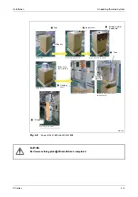


Set up the robot arm
Installation
3 - 18
3.3.2 Set
up
the SCARA robot
RH-1FRHR5515
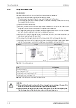
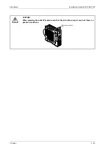
The table below shows how to set up and fix the SCARA robot RH-1FRHR5515.
The base area of the robot arm has been levelled by machine.
If the base area is too uneven then this may result in robot arm malfunctions.
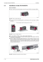
Fix the robot arm above the assembly boreholes on the four outer edges of the base area using
the supplied Allen head screws.
Align the robot arm horizontally.
The average surface finish of the assembly surface should be Ra = 6.3 μm. If the surface is too
rough then this may result in deviations in the position of the robot arm.
To avoid position deviations, the peripheral equipment that the robot accesses as well as the robot
arm itself should be installed on a common assembly platform/area.
The base area must be designed so that no distortion can occur, even from the loads and
vibrations emanating from the robot itself.
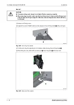
Only remove the transportation tool and the transport locks after setting up the robot arm.
High loads and strains occur on the base area when operating the robot at high speeds. Make
sure that the base area is suitable for the high forces and moments, as listed in Tab. 3-4.
Robot arm
Fixture
View from below
RH-1FRHR5515
R002698E
R002699E
Tab. 3-3:
Set up the robot arm
Load
RH-1FRHR5515
Moment of tilt M
L
[Nm]
610
Torsional moment M
T
[Nm]
807
Translational forces on horizontal plane F
H
[N]
1575
Translational forces on vertical plane F
V
[N]
712
Tab. 3-4:
Reaction forces on the base area of the robot
E
CAUTION:
●
When installing the robot, make sure that there is enough space remaining at the rear of the
robot arm to connect the cable used and to replace the backup battery.
●
And don't install the robot arm in the position where direct rays or the heat of lighting hits.
The skin temperature of the robot arm may rise, and the error may occur.
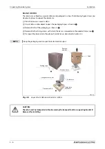
Snap ring
Washer
Fixing
screws (4)
M8 x 40 Allen
screw
㻝㻞㻞
㻝㻞㻞
㻝㻞㻜
㻔㻝㻡㻤㻕
㻞㻜㻜
㻤㻜
㻾㼦
㻞㻡
㻾㼦㻞㻡
㻞㻠㻜
㻞㻜㻜
㻞㻜
㻜
㻞㻠㻞
㻞㻤㻜
㻞㻞㻜
Installation side
(standard)
4-
∅
16 fixing boreholes
2-
∅
6 positioning boreholes
Содержание MELFA RH-FRH-D
Страница 2: ......
Страница 4: ......
Страница 6: ......
Страница 16: ...Contents X ...
Страница 22: ...Environmental conditions for operation Introduction 1 6 ...
Страница 70: ...Grounding the robot system Installation 3 32 ...
Страница 90: ...Teaching Box connection Connection 4 20 ...
Страница 96: ...Switch on the robot system Startup 5 6 ...
Страница 128: ...Dimensions Appendix A 18 ...
Страница 130: ...A 20 Index Appendix ...
Страница 131: ......
Страница 132: ......
Страница 133: ......
Страница 134: ......
Страница 135: ......
Страница 136: ......
Страница 137: ......
Страница 138: ......
Страница 139: ......
Страница 140: ......
Страница 141: ......
Страница 142: ......
Страница 143: ......
Страница 144: ......
Страница 145: ......
Страница 146: ......
Страница 147: ......
Страница 148: ......
Страница 149: ......
Страница 150: ......
Страница 151: ......
Страница 152: ......
Страница 153: ......
Страница 154: ......
Страница 155: ......
Страница 156: ......
Страница 157: ......
Страница 158: ......
Страница 159: ......
Страница 160: ......
Страница 161: ......
Страница 162: ......
Страница 163: ......
Страница 164: ......
Страница 165: ......