


Operation of Teaching Box (R32TB)
Move robot in JOG mode
FR series
6 - 9
6.4
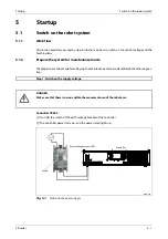
Move robot in JOG mode
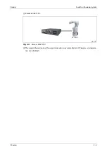
The robot can be moved in steps by the JOG mode. This section describes the JOG mode based on a
6-axis vertical articulated arm robot. Axis configuration depends on the robot type used. A detailed
description on the individual types of robot is contained in the technical manual of the respective ro-
bot.
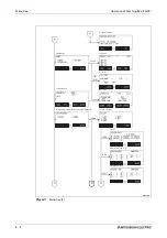
6.4.1 JOG
modes
There are 5 JOG modes:
Operating mode
Mode
Description
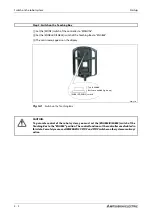
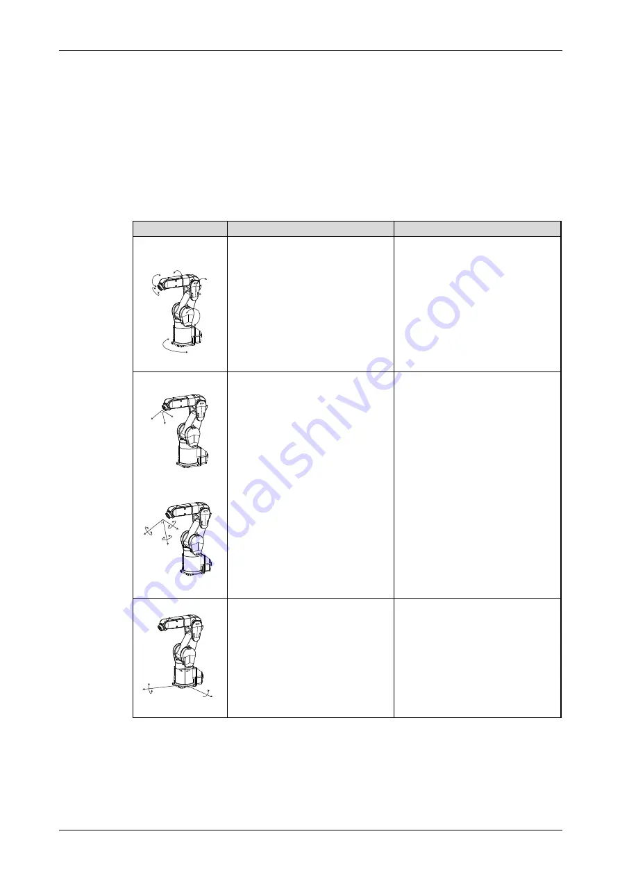
Articulated joint JOG
mode
R002731E
l
Set the [MODE] switch of the
Teaching Box to "ENABLE".
l
Keep the three-step switch in the middle
position.
l
Then press the [SERVO] key. (The servo
power supply is switched on).
l
Press [JOG]- and the [F1] key to switch to
articulated joint JOG mode.
l
To move the articulated joints, press
appropriate keys J1 to J6.
The axes of the robot can be moved individu-
ally in articulated joint JOG mode. This allows
axes J1 and J6 and auxiliary axes J7 and J8 to
be set independently. The number of axes
depends on the type of robot.
Auxiliary axes J7 and J8 are controlled by keys
[J1] and [J2].
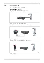
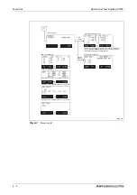
Tool JOG mode
R002732E
R002733E
Execute the three points listed above.
l
Press the function key to switch to the tool
JOG mode.
l
To move the axes, press appropriate key X,
Y, Z, A, B, C.
The position of the tipped tool can be moved
along the axes in the tool coordinate system in
tool JOG mode.
The tipped tool is moved linearly. The position
of the robot can be rotated by keys A, B and C
around axes X, Y and Z of the tool coordinate
system without changing the position of the
tipped tool. The middle point of the tool must
be set by parameter MEXTL.
The tool coordinate system in which the posi-
tion of the tipped tool is determined depends
on the robot type. In case of vertical articu-
lated arm robots, the direction from the grip-
per flange to the tipped tool is defined as +Z.
In case of SCARA robots, the direction up-
wards from the assembly area is defined as +Z.
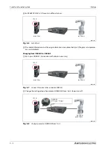
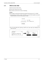
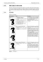
XYZ JOG mode
R002734E
Execute the three points listed above.
l
Press the function key to switch to the XYZ
JOG mode.
The position of the tipped tool can be moved
along the axes in the XYZ coordinate system in
XYZ JOG mode.
The position of the robot can be rotated by
keys A, B and C around axes X, Y and Z of the
XYZ coordinate system without changing the
position of the tipped tool. The middle point
of the tool must be set by parameter MEXTL.
Tab. 6-1:
JOG modes (1)
+J6
-J6
-J5
+J5
+J1
-J1
-J2
+J2
-J3
+J3
+J4
-J4
+Z
+Y
+X
+C
-C
-B
+B
+A
-A
+C
-C
+Z
+X
-A
+A
+Y
+B
-B
Содержание MELFA RH-FRH-D
Страница 2: ......
Страница 4: ......
Страница 6: ......
Страница 16: ...Contents X ...
Страница 22: ...Environmental conditions for operation Introduction 1 6 ...
Страница 70: ...Grounding the robot system Installation 3 32 ...
Страница 90: ...Teaching Box connection Connection 4 20 ...
Страница 96: ...Switch on the robot system Startup 5 6 ...
Страница 128: ...Dimensions Appendix A 18 ...
Страница 130: ...A 20 Index Appendix ...
Страница 131: ......
Страница 132: ......
Страница 133: ......
Страница 134: ......
Страница 135: ......
Страница 136: ......
Страница 137: ......
Страница 138: ......
Страница 139: ......
Страница 140: ......
Страница 141: ......
Страница 142: ......
Страница 143: ......
Страница 144: ......
Страница 145: ......
Страница 146: ......
Страница 147: ......
Страница 148: ......
Страница 149: ......
Страница 150: ......
Страница 151: ......
Страница 152: ......
Страница 153: ......
Страница 154: ......
Страница 155: ......
Страница 156: ......
Страница 157: ......
Страница 158: ......
Страница 159: ......
Страница 160: ......
Страница 161: ......
Страница 162: ......
Страница 163: ......
Страница 164: ......
Страница 165: ......