


58
Tension control parameter setting
procedure
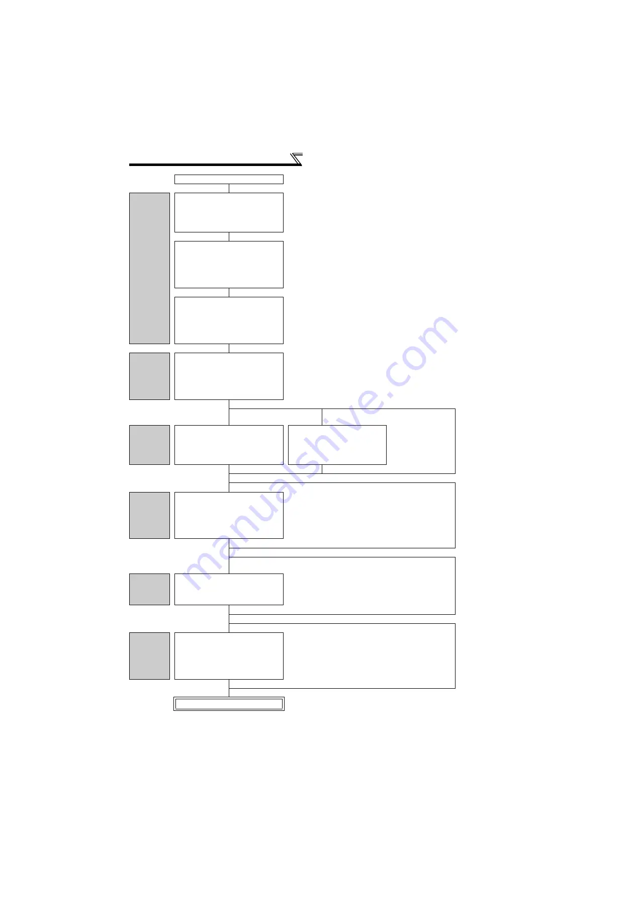
Continued from the last page.
Winding
diameter
compensation
setting
Set winding diameters.
Pr. 720 Maximum winding diameter 1
=
"maximum winding diameter"
Pr. 721 Minimum winding diameter 1
=
"minimum diameter"(Refer to
page 35
Set a sampling time for the winding
diameter calculation.
Pr. 707 Sampling time for winding
diameter calculation
= "0.01 to 1s"
Pr. 786 Number of averaging for winding
diameter calculation
= "4". (Refer to
page 38
Extend the sampling time and
increase the averaging count to
reduce fluctuation of winding
diameter compensation.
Set a maximum change amount per
sampling for the winding diameter
calculation result.
Set
Pr. 771 r-r' limit value (diameter)
according to the material to be winded.
(Refer to
page 38
Gear ratio
setting
When a reduction gear is used
between the roller shaft and the output
motor shaft, set a gear ratio with
Pr. 773 Gear ratio numerator (driver side)
and
Pr. 774 Gear ratio denominator
(follower side)
.(Refer to
page 34
Setting the taper ratio with
parameter.
Setting the taper ratio with
analog input.
Without the
taper ratio
setting.
Taper ratio
setting
Set a taper ratio in
Pr. 787 Taper ratio
setting
.
(Refer to
page 61
Set
Pr. 787
= "9999" and
Pr. 785
"2". Also set an analog input
terminal with
Pr. 733
.
(Refer to
page 18
.)
Calibrate a terminal in
the same calibration
procedure as for the set
point input.
(Refer to
page 29
Using the inertia compensation function.
Without the
inertia
compensation
function.
Inertia
compensation
setting
Assign the X57 and X58 signals to input
terminals.
Set
Pr. 20, Pr. 713, and Pr. 714 to Pr. 716
.
(Refer to
page 62.
)
Set "57 or 58" in any of
Pr. 178 to Pr. 189 (input terminal
function selection)
.
Set the operation frequency at minimum diameter (the
maximum operation frequency during tension control) in
Pr. 20
.
Set "(inertia moment of the motor + inertia moment of the
empty bobbin)
4" in
Pr. 713
.
Using the mechanical loss
compensation function.
Without the
mechanical loss
compensation
function.
Mechanical
loss
compensation
setting
Use
Pr. 739 to Pr. 749
to set the
mechanical loss setting value for each
operation frequency.
(Refer to
page 64.
)
For the mechanical loss values, use the monitored torque
at which the machine is driven with an empty bobbin.
Using the stall operation.
Without the stall
operation.
Stall
operation
setting
Assign the X92 signal to an input
terminal.
Set
Pr. 737, Pr. 738, Pr. 760.
(Refer to
page 65
Set "92" in any of
Pr. 178 to Pr. 189 (input terminal function selection)
.
For
Pr. 737
, set the torque to be used during stall operation.
For
Pr. 738
, set the speed limit to be used during stall
operation.
For
Pr. 760
, set the acceleration time to the speed limit to
be used during stall operation.
Test run


