29
Dancer control detail
3.7.3
Adjustment of target position input (Pr. 708, C3, C4, C6, C7, C13, C15, C31, C33)
* The parameter number in parentheses is the one for use with the parameter unit (FR-PU04/FR-PU07).
Position signal from dancer roll can be filtered by setting
Pr. 708
.
Set the time constant of the first-order lag filter. Set a large time constant when you want to delay the tracking of the speed
command, when the analog input voltage fluctuates, etc.
Above parameters can also be used to calibrate the signal of each terminal.
3.7.4
Measured value upper/lower limit detection signal (Pr. 131, Pr. 132)
When the measured value exceeds PID upper limit
(Pr. 131)
, PID upper limit (FUP) signal is output. Likewise, when
measured value falls below PID lower limit
(Pr. 132)
, PID lower limit (FDN) signal is output. Set each limit in parameter.
For output signals, assign "14, 114 (FDN)" or "5, 115 (FUP)" to any of
Pr. 190 to 196 (output terminal function selection)
.
3.7.5
PID gain switchover (Pr. 138, Pr. 270 to Pr. 278, Pr. 464 to Pr. 481, X89 signal, X90 signal)
(1) Second to fourth PID gain switchover
PID gain can be switched by ON/OFF of X89 signal and X90 signal.
Set "89(X89)" and "90(X90)" in
Pr. 178 to 189 (input terminal function selection)
to assign X89 and X90 signals.
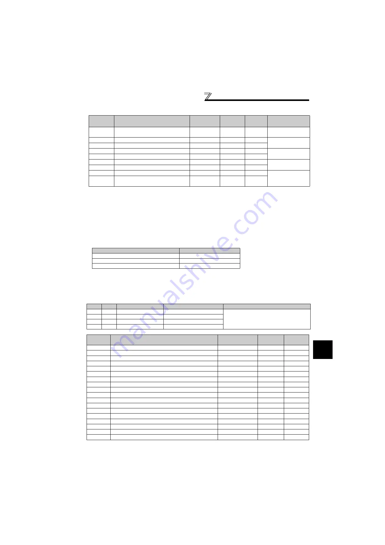
Parameter
Number
Name
Setting Range Increments
Initial
Value
Remarks
708
Filter time constant for dancer control
input
0 to 5s
0.001s
0s
C3(902)
Terminal 2 frequency setting bias
0 to 300%
0.1%
0%
Calibration of terminal 2
C4(903)
Terminal 2 frequency setting gain
0 to 300%
0.1%
100%
C6(904)
Terminal 4 frequency setting bias
0 to 300%
0.1%
0%
Calibration of terminal 4
C7(905)
Terminal 4 frequency setting gain
0 to 300%
0.1%
100%
C13(917)
Terminal 1 bias (speed)
0 to 300%
0.1%
0%
Calibration of terminal 1
C15(918)
Terminal 1 gain (speed)
0 to 300%
0.1%
100%
C31(926)
Terminal 6 bias (speed)
0 to 300%
0.1%
0%
Calibration of terminal 6
(for plug-in option FR-
A7AZ)
C33(927)
Terminal 6 gain (speed)
0 to 300%
0.1%
100%
Pr. 131, Pr. 132
setting
Limit value
600%
+100%
500%
0%
400%
-100%
X89
X90
PID gain switchover
Parameters selected
Remarks
OFF
OFF
(First) PID gain
Pr. 129, Pr. 130, Pr. 134 to Pr. 137
When set to 9999, first PID gain is selected.
ON
OFF
Second PID gain
Pr. 464 to Pr. 469
OFF
ON
Third PID gain
Pr. 470 to Pr. 475
ON
ON
Fourth PID gain
Pr. 471 to Pr. 481
Parameter
Number
Name
Setting Range
Increments
Initial Value
464
Second PID proportional band
0.1 to 1000%, 9999
0.1%
9999
465
Second PID integral time
0.1 to 3600s, 9999
0.1s
9999
466
Second PID differential time
0.01 to 10s, 9999
0.01s
9999
467
Second PID proportional band for under-set point value
0.1 to 1000%, 9999
0.1%
9999
468
Second PID integral time for under-set point value
0.1 to 3600s, 9999
0.1s
9999
469
Second PID differential time for under-set point value
0.01 to 10s, 9999
0.01s
9999
470
Third PID proportional band
0.1 to 1000%, 9999
0.1%
9999
471
Third PID integral time
0.1 to 3600s, 9999
0.1s
9999
472
Third PID differential time
0.01 to 10s, 9999
0.01s
9999
473
Third PID proportional band for under-set point value
0.1 to 1000%, 9999
0.1%
9999
474
Third PID integral time for under-set point value
0.1 to 3600s, 9999
0.1s
9999
475
Third PID differential time for under-set point value
0.01 to 10s, 9999
0.01s
9999
476
Fourth PID proportional band
0.1 to 1000%, 9999
0.1%
9999
477
Fourth PID integral time
0.1 to 3600s, 9999
0.1s
9999
478
Fourth PID differential time
0.01 to 10s, 9999
0.01s
9999
479
Fourth PID proportional band for under-set point value
0.1 to 1000%, 9999
0.1%
9999
480
Fourth PID integral time for under-set point value
0.1 to 3600s, 9999
0.1s
9999
481
Fourth PID differential time for under-set point value
0.01 to 10s, 9999
0.01s
9999


