74
••••••••••••••••••••••••••••••••••••••••••••••••••••••••••••••••••••••••••••••••••••••••••••••••••••••••••••••••••••••••••••••••••••••••••••••••••••••••••
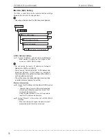
This menu is used to set the communication settings be-
tween this unit and the external device connected.
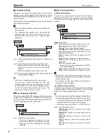
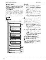
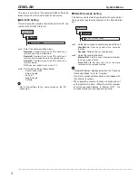
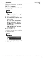
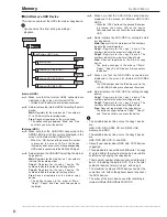
RS-232C Setting
This item is used to remotely control this unit via a PC con-
nected to the RS-232C terminal.
RS-232C Setting
1
COM/LAN
1
System Menu
step
1.
Select the communication mode.
Remote A
: Controls this unit via a PC and this unit
returns every status information.
Remote B
: Controls this unit via a PC and this unit
returns only the response to the command code.
Remote C
: Controls this unit via a PC and this unit
returns nothing.
Off
: Does not control this unit via a PC.
step
2.
Set the port settings shown below.
• Transmission mode
• Data bit length
• Parity bit
• Stop bit length
• Delimiter
• Set all the settings to the same values as the PC
connected.
COM/LAN
System Menu
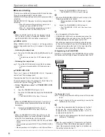
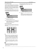
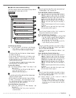
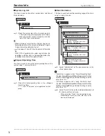
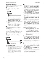
RS-485 Cascade Setting
This item is used to make the settings for the cascade func-
tion using the recorders connected via the RS-485 termi-
nal.
RS-485 Cascade Setting
2
COM/LAN
1
System Menu
step
1.
Select the cascade connection mode of this unit.
Standalone
: Does not perform the cascade
function.
Cascade
: Performs the cascade function.
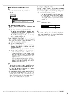
step
2.
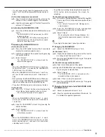
Select the recorder address.
Master ID:01
: Sets this unit as the master recorder
for the cascade function.
Slave ID:01 to 16
: Sets this unit as the slave
recorder for the cascade function.
• “Recorder Address” displays only when the “Cascade
Connection Mode” is set to “Cascade.”
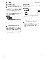
• Do not set cascade address which is overlapped with
that of other recorders.
• When operating cascade function via keyboard, set
all the recorders to slave. (When there is the recorder
of which cascade address is “Master ID:01,” the
cascade function may not operate correctly.)
Содержание 16CH DIGITAL RECORDER DX-TL5000U
Страница 143: ...872C355B2 PRINTED IN MALAYSIA ...

