
9
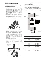
14.
Fit the shower fittings, refer to your shower
fittings installation and user guide for
instructions.
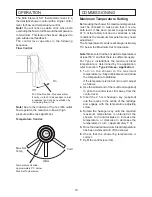
Note!
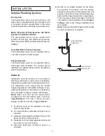
For high pressure systems (above
0.5 bar) make sure that the flow regulator
(supplied) is fitted inside the outlet nipple (refer
to illustration).
Important!
The fitting of this flow regulator will
invalidate any TMV2 low pressure compliance
due to the minimum flow rate requirements. Do
not fit the flow regulator in TMV2 low pressure
applications.
15.
Turn on the hot and cold water supplies and
check for leaks.
16.
Before using the shower, refer to section:
‘Commissioning’
.
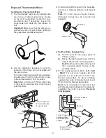
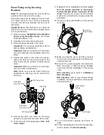
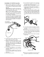
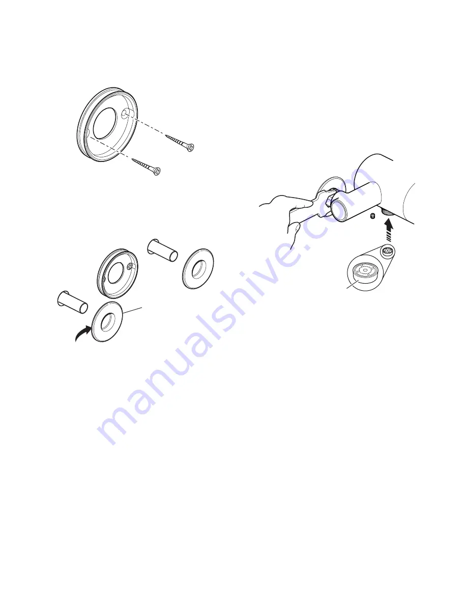
6.
Remove the backplate from the mixer by
loosening the grubscrew with a 2.5 mm
hexagonal key.
7.
Secure the backplate to the wall using the
screws.
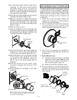
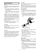
8. For Rear Entry Supplies Only:
Fit the concealing plates over the inlet pipes.
Note!
Apply silicone sealant to the back face
of the flange.
Apply Silicone Sealant
Concealing Plate
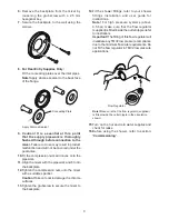
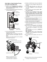
9. Caution! It is essential at this point
that the supply pipework is thoroughly
flushed through before connection to the
mixer.
Failure to do so may result in product
malfunction and will not be covered under the
guarantee.
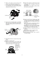
10.
Fit the compression nuts and olives onto the
pipework.
11.
Align the mixer with the pipework and fit onto
the backplate.
12.
Tighten the compression nuts onto the mixer
with a suitable spanner.
Caution!
Take care not to damage the chrome
surfaces.
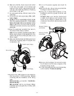
13.
Tighten the grubscrew to secure the mixer to
the backplate.
Note!
Make sure that the flow regulator (supplied)
is fitted inside the outlet nipple in the orientation
shown.
Flow Regulator
Содержание Element SLT
Страница 27: ...27 NOTES...


