

15
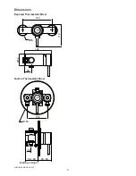
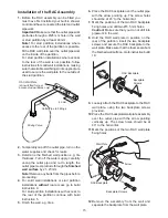
Installation of the RAC Assembly
1.
Before the RAC assembly can be fitted you
must have first installed your built-in shower
control and have connected the inlet and outlet
pipework.
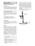
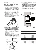
Important!
Make sure that the outlet pipework
protrudes through a Ø25 mm hole in the wall
or stud partition by at least 40 mm.
Note!
For stud partition installations where
access to the rear of the partition is possible,
fit the RAC wall plate over the outlet pipework
on the inside of the partition.
For stud partition installations where access
to the rear of the wall is not possible, follow
instructions for solid wall installations, making
sure that suitable wall fixings (not supplied) are
used to secure the wall plate to the outside of
the stud partition.
40 mm
RAC Wall Plate
(shown fitted for rear
access stud partitions only)
Outlet Pipe to Fittings
Mixing Valve
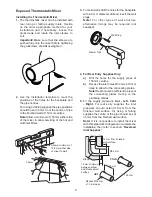
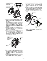
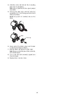
2.
Temporarily cap off the outlet pipe, turn on the
water supplies and check for leaks.
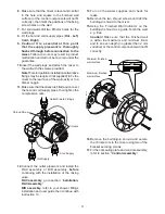
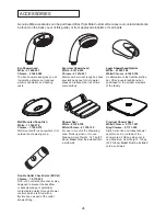
3.
Determine the finished wall position e.g. tile
thickness. Turn off the water supply, carefully
uncap the outlet pipe and cut to length, the
outlet pipe must protrude through the
finished
wall surface
by 21–23 mm.
Note!
Remove any burrs from the pipes before
proceeding.
4.
For solid wall installations or stud partition
installations
without
rear access go to build
instruction 9.
For stud partition installations with access to
the rear of the partition continue with build
instruction 5.
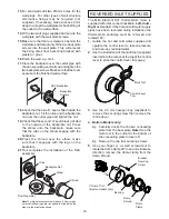
5.
Finish the wall, e.g. tiles.
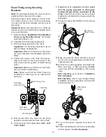
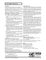
6.
Place the RAC backplate over the outlet pipe
with the arrow pointing up. The screw holes
should be at 45° to the horizontal.
7.
Mark the positions of the two RAC backplate
fixing holes and drill two Ø5.5 mm holes.
Caution!
Make sure that you do not drill into
pipework in the wall.
8.
Hold the RAC wall plate in position on the
rear of the partition, insert the two backplate
screws and secure the RAC backplate to the
wall plate. Make sure that the foam seal abuts
the finished wall surface. Go to instruction build
18.
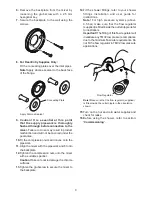
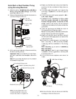
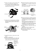
9.
Loosely attach the RAC backplate to the RAC
wall plate, using the two backplate screws
provided.
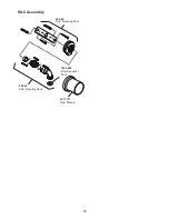
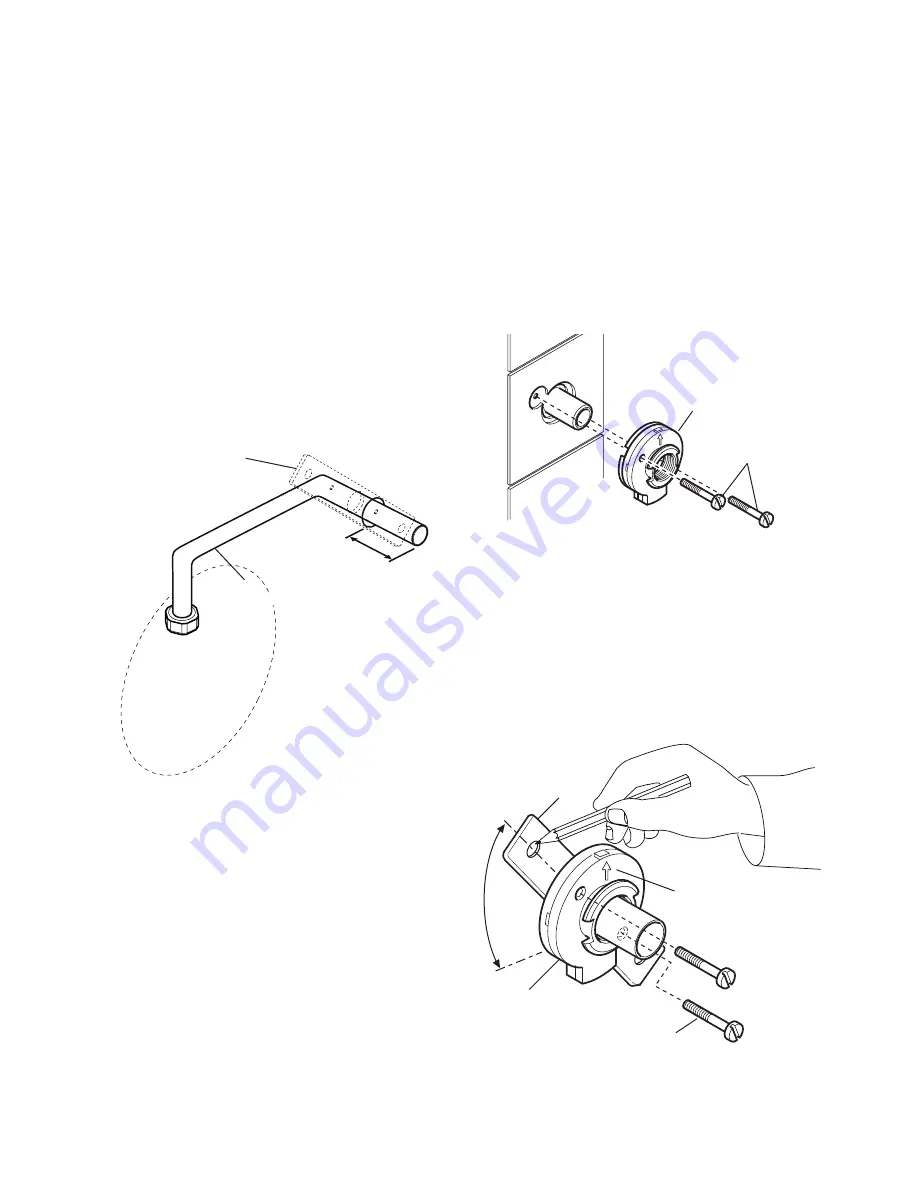
10.
Place the RAC backplate/wall plate assembly
over the outlet pipe with the arrow pointing
vertically up. The screw holes should be at
40° to the horizontal.
11.
Mark the positions of the two RAC wall plate
fixing holes.
12.
Remove the assembly from the wall and
separate the backplate from the wall plate.
RAC Backplate
Backplate
Screws
Wall Plate
RAC Backplate
Backplate Screws
Arrow
40°
Содержание Element SLT
Страница 27: ...27 NOTES...


