8
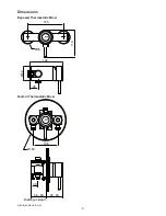
Exposed Thermostatic Mixer
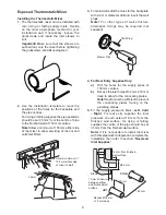
Installing the Thermostatic Mixer
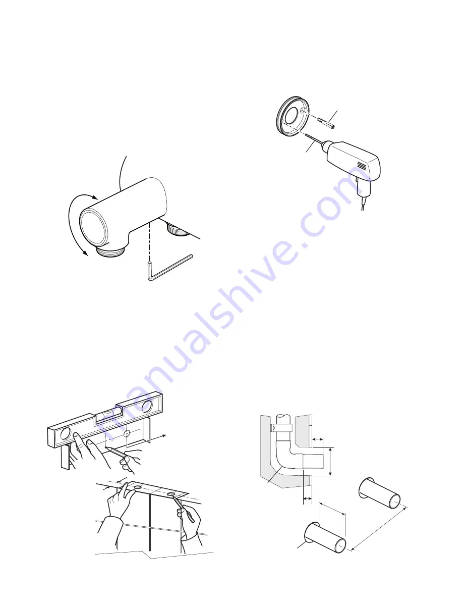
1.
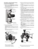
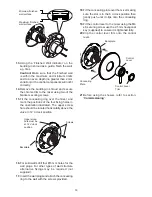
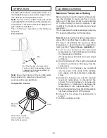
The thermostatic mixer can be installed with
rear, rising or falling supply inlets. Decide
on the most appropriate method for your
installation and if necessary, loosen the
grubscrews and rotate the inlet elbows to
suit.
Important!
Make sure that the elbows are
pushed fully onto the mixer before tightening
the grubscrews,
do not
overtighten.
2.
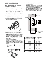
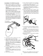
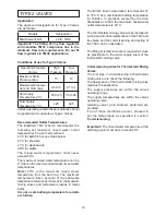
Use the installation template to mark the
positions of the holes for the backplate and
the pipe centres.
For rising or falling supplies the pipe positions
should be set 35 mm from the centre of pipe
to the finished wall at 153 mm centres.
Note!
Allow a minimum of 150 mm either side
of the mixer to allow servicing of the hot and
cold inlet filters.
Allow a minimum of
150 mm either side
of mixer to wall
35 mm
3.
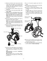
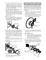
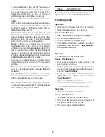
For solid walls drill the holes for the backplate
with a 6 mm diameter drill and insert the wall
plugs.
Note!
For other types of wall structure
alternative fixings may be required (not
supplied).
Wall Plug
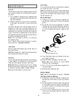
4. For Rear Entry Supplies Only:
a)
Drill the holes for the supply pipes at
153 mm centres.
b)
Recess the inlet holes Ø32 mm x 10 mm
deep to allow for the concealing plates.
Note!
Depth must be sufficient to prevent
the concealing plates fouling on the
plumbing elbows.
5.
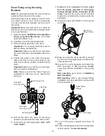
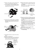
Fit the supply pipework:
Hot - Left, Cold
- Right.
For rear entry supplies the inlet
pipework should extend 18 mm from the
finished wall surface, for rising or falling
supplies the centre of the pipe should be set
35 mm from the finished wall surface.
Note!
If it is not possible to install the mixer
with this pipework configuration complete the
installation then refer to section:
‘Reversed
Inlet Supplies’
.
Ø6 mm Drill
10 mm minimum
between elbow
and finished wall
surface
Ø32 mm
18 mm from finished
wall surface
Elbow
Recess Ø32 mm
x 10 mm deep
18 mm
153 mm
HOT
COLD
Содержание Element SLT
Страница 27: ...27 NOTES...


