


3-10 System Installation
3.4
Installing Peripherals
For the models of the supported peripherals, please refer to “2.1.3 Supported Peripherals”.
3.4.1
Footswitch Installation
1. Connecting: insert the USB connector to the system applicable USB ports (in the rear
of the machine or left of control panel).
2. For settings of footswitch, please refer to 3.5.3 System Preset.
3.4.2
Installing a Graph / Text Printer
3.4.2.1
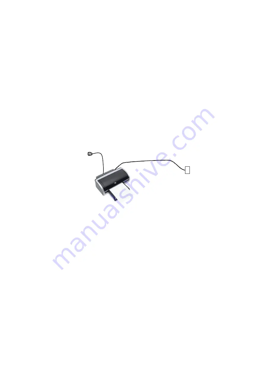
Connecting a Local Printer
As shown in the figure below, a graph / text printer has a power cord and data cable. The
power cord shall be directly connected to a wall receptacle as required.
1. Connect the data cable with the USB port on the ultrasound system.
2. Connect the power cord to an appropriate power supply that is well grounded.
3. Power on the system and the printer.
4. Check the printer status:
Enter [Setup]-> [Print Preset]->
“Printer Driver” page, printers that are installed
automatically will be displayed in the list with the “Status” of “Ready”.
Data cord
USB port
Power cord
Содержание DC-25
Страница 1: ...DC 32 DC 30 DC 28 DC 26 DC 25 Digital Ultrasound System Service Manual Revision 11 0 ...
Страница 2: ......
Страница 7: ...v Appendix C Requirements of Performance Indices C 1 Appendix D Boot Screen D 1 ...
Страница 8: ......
Страница 12: ......
Страница 70: ......
Страница 88: ...5 18 Function Checking and Testing ...
Страница 94: ...6 6 Software installation and Maintenance ...
Страница 168: ......
Страница 178: ......
Страница 190: ......
Страница 206: ......
Страница 211: ...Boot Screen D 1 Appendix D Boot Screen BIOS Boot Screen LINUX Boot Screen ...
Страница 212: ...D 2 Boot Screen Doppler Boot Screen ...
Страница 213: ...P N 046 009019 00 11 0 ...


