


E a s y P I C v 8 f o r P I C 2 4 / d s P I C 3 3
M a n u a l
P A G E 9
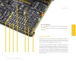
Voltage reference
The PSU is able to provide a very accurate, programmable voltage reference (VREF)
(5)
in the range from 0V to
4.096V. VREF is very useful for many different applications including A/D and D/A converters, comparators,
etc.
The programmable VREF design is based on several different ICs produced by Microchip: the MCP1501, a
high-precision buffered voltage reference IC is used to provide a very precise VREF of 4.096V for the MCP4726,
a 12-bit D/A converter (DAC) with integrated EEPROM. The MCP4726 DAC is controlled and programmed by
the CODEGRIP module, over the I2C interface. Finally, the MCP606, a single rail-to-rail operational amplifier
is used to provide an additional buffering at the output. By using a 4-pole DIP switch
(6)
located in the VREF
section of the development board, it is possible to route
VREF
to four different MCU pins:
ON (up):
connects VREF to the MCU pins (RB0, RB3, RB4, and RB6)
OFF (down):
disconnects VREF from the MCU pins (RB0, RB3, RB4, and RB6)
Programming voltage
Not all PIC24/dsPIC33 MCU devices support low voltage programming. Therefore, the PSU module has to
provide the required high voltage (VPP) for the programming of such devices. The VPP is controlled by the
CODEGRIP module automatically, it depends on the programmed MCU and can’t be modified by the user. To
provide a sufficient voltage level, the MIC2250, a high-efficiency, low EMI boost regulator is used. It is used
to provide 14V for the operational amplifier circuit composed of a dual operational amplifier, labeled as
MCP6H02T, and produced by Microchip. This circuit has a fixed gain, allowing the CODEGRIP programmer/
debugger module to reach up to 14V for the high-voltage programming of various PIC24/dsPIC33 MCU
devices.
ADC INPUT
A/D converters are specialized circuits which can convert analog signals (voltages) into a digital
representation, usually in form of an integer number. The value of this number is linearly dependent on the
input voltage value. Most microcontrollers nowadays internally have A/D converters connected to one or
more input pins.
EasyPIC v8 for PIC24/dsPIC33 provides an interface in form of a potentiometer for simulating analog input
voltages that can be routed to any of the 10 supported analog input pins. In order to connect the output of
the potentiometer P1
(7)
to RB0, RB1, RB14, RB15 analog microcontroller inputs, you have to place the DIP
switch SW7
(8)
in the desired position.
SW7 (ADC IN):
UP position:
potentiometer is connected to the respective MCU pin
DOWN position:
potentiometer is disconnected from the respective MCU pin
P A G E 9
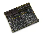
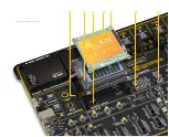
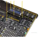
P O W E R S U P P L Y
Figure 1: P
ow
er supply unit view
N O T E
E a s y P I C v 8 for P I C 2 4 / d s P I C 3 3
M a n u a l
6
7
8
5
In order to protect host MCU and development board, VREF values higher then 3.3V
can only be set if the board voltage is previously set to 5V.
Содержание EasyPIC V8
Страница 4: ...P A G E 4 E a s y P I C v 8 f o r P I C 2 4 d s P I C 3 3 M a n u a l...
Страница 24: ...Figure 10 1x16 display header view 1 4 2 3...
Страница 33: ......


