


P A G E 18
E a s y P I C v 8 f o r P I C 2 4 / d s P I C 3 3
M a n u a l
7
2
6
4
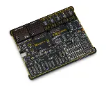
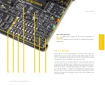
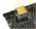
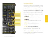
Figure 7: Main board with MCU socket section view
MCU sockets
As previously mentioned, the EasyPIC v8 for PIC24/dsPIC33 development board
supports all 16-bit PIC24/dsPIC33 MCUs in DIP package type. There are seven
different sockets, ranging from DIP14 (14-pin DIP socket), up to DIP28 (28-pin DIP
socket). All DIP sockets are grouped in the lower left area of the board
(1)
.
Only a single DIP socket should be populated at a time since their lines are shared.
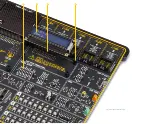
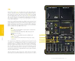
Each DIP socket allows an MCU with the specific pin-count to be used. For example, if
using a 28-pin MCU, it should be placed into the one of the DIP28 sockets, exclusively
(i.e. placing an 18-pin MCU into the DIP28 socket will cause pin misalignment and
other problems). However, there are exceptions to this rule: if using an MCU in DIP28
package type, there are three options available, depending on its pinout: DIP28A,
DIP28B and DIP28C. To determine the correct socket that should be used in this case,
the pinout of the MCU should be compared with the pinout which is printed next to
these sockets.
How to install the MCU into the DIP socket?
First make sure that a half circular cut in the microcontroller DIP packaging matches
the cut in the DIP socket
(2)
. Align both ends of the microcontroller with the socket.
Then put the microcontroller slowly down until all the pins match the socket. Check
again if everything is placed correctly and gently press the microcontroller until it is
completely plugged into the socket.
3
1
5
Only a single MCU must be installed into the development board at a time.
Содержание EasyPIC V8
Страница 4: ...P A G E 4 E a s y P I C v 8 f o r P I C 2 4 d s P I C 3 3 M a n u a l...
Страница 24: ...Figure 10 1x16 display header view 1 4 2 3...
Страница 33: ......


