


P A G E 28
E a s y P I C v 8 f o r P I C 2 4 / d s P I C 3 3
M a n u a l
COMMUNICA
TION
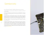
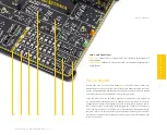
Communication
Communication connectors allow the development board to be connected with many
different devices that use high-layer communication protocols such as USB, CAN, etc.
Also, there is a USB-UART converter, which enables simplified communication with the
personal computer over the emulated serial interface. Each of these connectors will be
described in more detail, in the following sections of the manual.
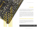
CAN
Controller Area Network (CAN or CAN Bus)
(8)
is a serial network technology, originally
designed for the automotive industry, but due to its robustness and noise immunity,
it has become popular in many other applications. The CAN Bus is primarily used in
embedded systems, allowing to establish fast communication between MCUs or other
peripherals, eliminating the need for expensive and complex technology. The CAN
Bus consists of only two wires, allowing both high data rates and message collision
prevention.
The EasyPIC v8 for PIC24/dsPIC33 utilizes the MCP2561FD
(9)
, a high-speed CAN
flexible data rate transceiver from Microchip, offering support for both CAN and
CAN FD (CAN Flexible Data Rate) for MCUs equipped with the CAN peripheral. Some
features provided by the MCP2561FD include:
∫
Optimized for CAN FD at 2Mbps, 5Mbps, and 8 Mbps operation
∫
CAN Bus Pins are disconnected when the CAN transceiver is unpowered
∫
Detection of ground fault
∫
Protection against damage due to short-circuit conditions
∫
Protection against high-voltage transients in automotive environments
∫
Automatic thermal shutdown
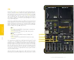
The development board offers a jumper located in the CAN COMM. section, which is
used to specify whether the MCU pins should be used as GPIOs or they should be
connected to the CAN transceiver circuit as CAN TX and CAN RX lines. CAN connectivity
is provided only for MCUs installed in DIP28A, DIP40A and DIP40B MCU sockets:
J17 (DIP28B)
(10)
GPIO (up):
Allows the RB14 and RB15 pins to be used as GPIO lines
CAN (down):
Connects the RB14 and RB15 pins to the CAN transceiver circuit
The development board can be connected to the CAN Bus by using the 2-pole screw
terminal
(11)
, located in the CAN COMM section. Please note that the CAN H and
CAN L differential signals need to be properly connected to the CAN Bus, else no CAN
communication will be possible.
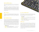
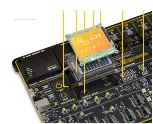
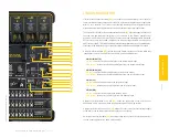
USB-UART
UART (Universal Asynchronous Receiver/Transmitter) interface
(1)
is one of the most
common interfaces for data exchange between the MCU and other external devices.
The EasyPIC v8 for PIC24/dsPIC33 development board offers the UART connectivity
over the USB-C connector
(2)
by utilizing the FT230XQ
(3)
, a popular USB-UART signal
conversion IC, produced by FTDI Chip. FT230XQ drivers are available for download
from the official FTDI drivers web page
www.ftdichip.com/Drivers/VCP.htm
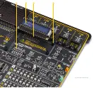
Two four-pole DIP switches located in the USB TO UART section of the board, labeled as
TX (SW3)
(4)
and RX (SW2)
(5)
, allow fully independent control of the UART RX and TX
lines, offering complete freedom of pin selection. The TX DIP switch (SW3) connects
the specific MCU pin (labeled next to the related switch) as the UART transmission
line, while the RX DIP switch (SW2) connects the specific MCU pin (labeled next to
the related switch) as the UART receiving line. This allows custom UART TX/RX pair
configuration, allowing the development board to adapt to many different UART pin
configurations, found on various PIC MCU devices:
SW3 (TX)
ON (up):
connects the respective UART TX pin to the USB-UART conversion circuit
OFF (down):
disconnects the respective UART TX pin from the USB-UART conversion circuit
SW2 (RX)
ON (up):
connects the respective UART RX pin to the USB-UART conversion circuit
OFF (down):
disconnects the respective UART RX pin from the USB-UART conversion circuit
UART traffic is indicated by two LED indicators, located in the USB TO UART section of
the board, near the USB-C connector:
Yellow LED (TX)
(6)
indicates outgoing data transfer
Red LED (RX)
(7)
indicates incoming data transfer
Содержание EasyPIC V8
Страница 4: ...P A G E 4 E a s y P I C v 8 f o r P I C 2 4 d s P I C 3 3 M a n u a l...
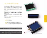
Страница 24: ...Figure 10 1x16 display header view 1 4 2 3...
Страница 33: ......


