


E a s y P I C v 8 f o r P I C 2 4 / d s P I C 3 3
M a n u a l
P A G E 7
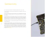
O V E R V I E W
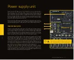
system (OS). The USB-C connector is also used to power the development board,
simplifying the cable management.
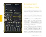
The EasyPIC v8 for PIC24/dsPIC33 development board offers
five improved mikroBUS
™
sockets
, allowing interfacing with a vast amount of electronic circuits and reference
designs, standardized under the Click board trademark. Click boards
™
are simple to
use, require no additional hardware configuration and can be easily connected to the
development board by inserting them into any of the available mikroBUS
™
sockets.
A new design of the mikroBUS
™
socket allows even easier interfacing with the Click
board
™
line of products: it has a sturdier design which helps to align the Click board
™
correctly. To read more about development improvements and huge benefits offered
by the mikroBUS
™
and Click board
™
line of products, visit the official Mikroe web page
at
www.mikroe.com
The EasyPIC v8 for PIC24/dsPIC33 development board is equipped with two display
connectors, located in the middle section of the board. One connector is a
1x16 pin
header
used for connecting a character-based LCD in 4-bit mode. The second display
connector is a single row 20 pin header, which supports monochromatic GLCD and
EasyTFT board. The
1x20 pin graphical display connector
is accompanied by two
4-pin connectors (4-pin FFC connector and 1x4 pin header), which are used for the
touch panel connection. The development board also provides the required circuitry,
allowing the resistive touch panel to be interfaced with the installed MCU. Both the LCD
and GLCD display connectors support a PWM-driven (dimmable) or fixed backlight
functionality.
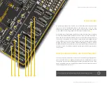
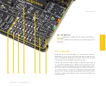
The
I/O section
occupies the lower part of the development board and contains
available MCU pins routed to 2x5 pin headers for easy access. There are configurable
pull-up or pull-down resistors and buttons for applying logic states to MCU pins. LED
indicators provide visual feedback of logic states for each pin. The MCU pins are divided
into groups, following the grouping concept used on the MCU itself (PORTA, PORTB).
The I/O section is where the most interaction with the MCU takes place.
Communication options
such as USB HOST/DEVICE, USB-UART, CAN are also included.
All the connectors are positioned at the edges of the development board, so they can
be easily accessed. This is also true for the power connectors, as well as for an external
RJ45 ICD connector. This allows clean and clutter-free cable management.
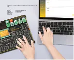
The EasyPIC v8 for PIC24/dsPIC33 development board is equipped with the onboard
CODEGRIP module and supported by a powerful CODEGRIP Suite
, enabling complete
control over the programming and debugging tasks. It is also used to configure
various other options and settings, providing visual feedback through its clean
and comprehensive Graphical User Interface (GUI). Detailed explanation on how to
configure and use the CODEGRIP module find at the following link:
www.mikroe.com/
debuggers/codegrip
Содержание EasyPIC V8
Страница 4: ...P A G E 4 E a s y P I C v 8 f o r P I C 2 4 d s P I C 3 3 M a n u a l...
Страница 24: ...Figure 10 1x16 display header view 1 4 2 3...
Страница 33: ......


