


E a s y P I C v 8 f o r P I C 2 4 / d s P I C 3 3
M a n u a l
P A G E 15
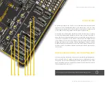
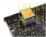
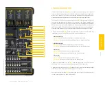
DBG selection
The EasyPIC v8 for PIC24/dsPIC33 development board is equipped with
the RJ-45 connector
(2)
, allowing an external programmer/debugger to
be connected. The connector supports a wiring pinout compatible with
Microchip
®
ICD external programmers/debuggers. This connector also
supports connection of the RJ-12 cable, connect the RJ-12 cable by simply
inserting it into the center of the RJ-45 connector.
1
2
3
4
5
6
7
1
MCLR
VDD
GND
PGD
PGC
2
3
4
5
6
8
RJ-45
RJ-12
ICSP (MHCP)
E X T P R O G / D B G P I N O U T
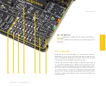
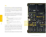
If using
DIP28B/C, DIP20A
or
DIP18
MCU sockets, a jumper with the
J12
label should be used to configure the programming lines:
J12 (DIP28B/C, DIP20A, DIP18)
GPIO (up):
allows the RB0 and RB1 pins to be used as GPIO lines
PGC/PGD (down):
connects the RB0 and RB1 pins to the CODEGRIP
programmer/debugger module or external device
If using
DIP20B
or
DIP14
MCU sockets, a jumper with the
J13
label should
be used to configure the programming lines:
J13 (DIP20B, DIP14)
GPIO (up):
allows the RA0 and RA1 pins to be used as GPIO lines
PGC/PGD (down):
connects the RA0 and RA1 pins to the CODEGRIP
programmer/debugger module or external device
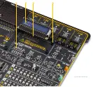
The DIP switch located next to the RJ-45 connector allows control of the
interface between onboard CODEGRIP module and target MCU:
ONBOARD (down):
Interface is enabled. If an external debugger probe-device
is connected, there is a possible collision in communication.
EXTERNAL (up):
Interface is disabled. External debugger probe-device can
reliably communicate with target MCU.
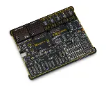
Figure 6: Programmer/debugger view
1
2
Содержание EasyPIC V8
Страница 4: ...P A G E 4 E a s y P I C v 8 f o r P I C 2 4 d s P I C 3 3 M a n u a l...
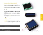
Страница 24: ...Figure 10 1x16 display header view 1 4 2 3...
Страница 33: ......


