


P A G E 10
E a s y P I C v 8 f o r P I C 2 4 / d s P I C 3 3
M a n u a l
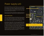
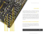
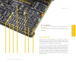
P O W E R S U P P L Y
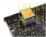
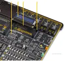
PSU connectors
As explained, the advanced design of the PSU allows several types of power sources to
be used, offering unprecedented flexibility: when powered by a Li-Po/Li-ION battery,
it offers an ultimate degree of autonomy. For situations where the power is an issue,
it can be powered by an external 12VDC power supply, connected over the 5.5mm
barrel connector. Power is not an issue even if it is powered over the USB cable. It can
be powered over the USB-C connector, using power supply delivered by the USB HOST
(e.g. personal computer), USB wall adapter, or a battery power bank.
There are three power connectors available, each with its unique purpose:
POWER/DEBUG
,
USB-C connector
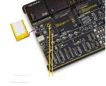
BATTERY
, standard 2.5mm pitch XH battery connector
POWER 12VDC
, barrel type male 2mm x 6.5mm power connector
Power/debug, USB-C connector
The development board can be powered over the USB-C connector, labeled as POWER/
DEBUG. This connector provides power from the USB host, USB power bank, or USB
wall adapter. When powered over the USB connector, the available power will depend
on the USB power source capabilities.
Maximum power ratings, along with the allowed input voltage range in the case when
the USB power supply is used, are given in the table below:
Power 12VDC, external power supply
An external 12V power supply can be connected over the 12VDC barrel connector.
When using an external power supply, it is possible to obtain an optimal amount of
power, since one external power supply unit can be easily exchanged with another,
while its power and operating characteristics can be decided per application. The
development board allows a maximum current of 2.8A per power rail (3.3V and 5V)
when using an external 12V power supply. The barrel-type connector is useful for
connecting wall-adapters.
Maximum power ratings, along with the allowed input voltage range in the case when
the external power supply is used, are given in the table below:
Figure 2: USB power supply table
USB Power Supply
Input Voltage [V]
Output Voltage [V]
3.3
5
3.3 & 5
1.8
1.4
0.8 & 0.8
6
7
6.64
Max Current [A]
Max Power [W]
MIN
4.4
5.5
MAX
When using a PC as a power source, the maximum power can be obtained if the host
PC supports the USB 3.2 interface and is equipped with USB-C connectors. If the host
PC has a USB 2.0 interface, it will be able to provide the least power, since only up to
500 mA (2.5W at 5V) is available from the host in that case. Note that when using
long USB cables or USB cables of low quality, the voltage may drop outside the rated
operating voltage range, causing unpredictable behavior of the development board.
N O T E
If the host PC is not equipped with the USB-C connector, a Type A to Type C USB
adapter may be used (included in the package).
Figure 3: External Power supply table
External Power Supply
Input Voltage [V]
Output Voltage [V]
3.3
5
3.3 & 5
2.8
2.8
2.8 & 2.8
9.24
14
23.24
Max Current [A]
Max Power [W]
MIN
10.6
14
MAX
Содержание EasyPIC V8
Страница 4: ...P A G E 4 E a s y P I C v 8 f o r P I C 2 4 d s P I C 3 3 M a n u a l...
Страница 24: ...Figure 10 1x16 display header view 1 4 2 3...
Страница 33: ......


