


All the products owned by MikroElektronika are protected by copyright law and international copyright treaty. Therefore, this manual is to be treated as any other copyright material. No
part of this manual, including product and software described herein, must be reproduced, stored in a retrieval board, translated or transmitted in any form or by any means, without
the prior written permission of MikroElektronika. The manual PDF edition can be printed for private or local use, but not for distribution. Any modification of this manual is prohibited.
MikroElektronika provides this manual ‘as is’ without warranty of any kind, either expressed or implied, including, but not limited to, the implied warranties or conditions of
merchantability or fitness for a particular purpose.
MikroElektronika shall assume no responsibility or liability for any errors, omissions and inaccuracies that may appear in this manual. In no event shall MikroElektronika, its directors,
officers, employees or distributors be liable for any indirect, specific, incidental or consequential damages (including damages for loss of business profits and business information,
business interruption or any other pecuniary loss) arising out of the use of this manual or product, even if MikroElektronika has been advised of the possibility of such damages.
MikroElektronika reserves the right to change information contained in this manual at any time without prior notice, if necessary.
TRADEMARKS
The MikroElektronika name and logo, the MikroElektronika logo, mikroC, mikroBasic, mikroPascal, CODEGRIP, EasyPIC, Click boards
™
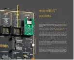
and mikroBUS
™
are trademarks of MikroElektronika.
All other trademarks mentioned herein are property of their respective companies.
All other product and corporate names appearing in this manual may or may not be registered trademarks or copyrights of their respective companies, and are only used for
identification or explanation and to the owners’ benefit, with no intent to infringe.
Copyright © MikroElektronika, 2021. All Rights Reserved.
HIGH RISK ACTIVITIES
The products of MikroElektronika are not fault – tolerant nor designed, manufactured or intended for use or resale as on – line control equipment in hazardous
environments requiring fail – safe performance, such as in the operation of nuclear facilities, aircraft navigation or communication boards, air traffic control, direct life
support machines or weapons systems in which the failure of Software could lead directly to death, personal injury or severe physical or environmental damage (‘High Risk
Activities’). MikroElektronika and its suppliers specifically disclaim any expressed or implied warranty of fitness for High Risk Activities.
D I S C L A I M E R
Содержание EasyPIC V8
Страница 4: ...P A G E 4 E a s y P I C v 8 f o r P I C 2 4 d s P I C 3 3 M a n u a l...
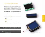
Страница 24: ...Figure 10 1x16 display header view 1 4 2 3...
Страница 33: ......


