V6-i VRF 50/60Hz
63
P
art
5
- Ele
ctric
al
C
ompon
en
ts and
Wi
ring Dia
gr
am
s
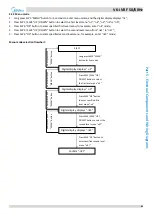
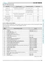
How to exit specified menu mode:
Table 5-2.4:
Exit specified menu mode method:
Menu mode
Manual exit method
Automatic exit method
System restart
Debug mode 1 (2)
Long press SW6 “OK” button when the digital
display is not in menu selection state
After running 120 minutes
Invalid
Maintenance mode
/
After running 60 minutes
Invalid
Backup run
/
After running 4 days or both
two compressors are failed
Invalid
Vacuum mode
Long press SW6 “OK” button when the digital
display is not in menu selection state
After running 8 hours
Invalid
Power limitation mode
Select power limitation mode 1 “n41”
/
Valid
Auto power save mode
Select “nb3”
/
Valid
Auto snow-blowing mode 1 (2)
Select “nb7”
/
Valid
VIP address setting
/
/
Valid
o
F /
o
C setting
/
/
Valid
UP / DOWN system check button
2.2.4
Before pressing UP or DOWN button, allow the system to operate steadily for more than an hour. On pressing UP or DOWN
button, the parameters listed in Table 5-2.5 will be displayed in sequence.
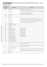
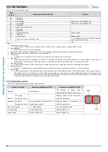
Table 5-2.5:
System check
DSP1
content
Parameters displayed on DSP2
Remarks
0.--
Unit address
For V6 Individual outdoor unit: 0
1.--
Unit capacity
Refer to Note 1
2.--
Number of outdoor units
For V6 Individual outdoor unit: 1
3.--
Number of indoor units as set on PCB
4.--
The capacity of outdoor unit
5.--
Total capacity requirement of indoor units
6.--
Total corrected capacity requirement of indoor units
7.--
Operating mode
Refer to Note 2
8.--
Outdoor unit actual operating capacity
9.--
Fan A speed index
Refer to Note 3
10.--
Fan B speed index
Refer to Note 3
11.--
Indoor heat exchanger pipe (T2/T2B) temperature (°C)
Actual value = value displayed
12.--
Main heat exchanger pipe (T3) temperature (°C)
Actual value = value displayed
13.--
Outdoor ambient (T4) temperature (°C)
Actual value = value displayed
14.--
Plate heat exchanger cooling refrigerant inlet (T6A) temperature (°C)
Actual value = value displayed
15.--
Plate heat exchanger cooling refrigerant outlet (T6B) temperature (°C)
Actual value = value displayed
16.--
Inverter compressor A discharge temperature (°C)
Actual value = value displayed
17.--
Inverter compressor B discharge temperature (°C)
Actual value = value displayed
18.--
Inverter module A heatsink temperature (°C)
Actual value = value displayed
19.--
Inverter module B heatsink temperature (°C)
Actual value = value displayed
20.--
Plate heat exchanger cooling refrigerant outlet temperature minus inlet temperature (°C)
Actual value = value displayed
21.--
Discharge superheat degree (°C)
Actual value = value displayed
22.--
Inverter compressor A current (A)
Actual value = value displayed
23.--
Inverter compressor B current (A)
Actual value = value displayed
24.--
EXVA position
Refer to Note 4
25.--
EXVB position
Refer to Note 4
26.--
EXVC position
Refer to Note 4
27.--
Compressor discharge pressure (MPa)
Actual value = value displayed × 0.1
28.--
Reserved
29.--
Number of indoor units currently in communication with the outdoor unit
Actual value = value displayed
30.--
Number of indoor units currently operating
31.--
Priority mode
Refer to Note 5
32.--
Silent mode
Refer to Note 6
33.--
Static pressure mode
Refer to Note 7
Table continued on next page …
Содержание MV6-i252WV2GN1-E
Страница 3: ...V5 X VRF 50 60Hz 2 Midea V6 i Series Service Manual...
Страница 33: ...V6 i VRF 50 60Hz 32 Midea V6 i Series Service Manual...
Страница 49: ...V6 i VRF 50 60Hz 48 Midea V6 i Series Service Manual...
Страница 50: ...V6 i VRF 50 60Hz 49 Part 4 Field Settings Part 4 Field Settings 1 Outdoor Unit Field Settings 50...
Страница 69: ...V6 i VRF 50 60Hz 68 Midea V6 i Series Service Manual...


