V6-i VRF 50/60Hz
57
P
art
5
- Ele
ctric
al
C
ompon
en
ts and
Wi
ring Dia
gr
am
s
20-32HP
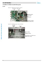
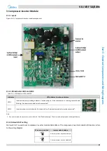
Figure 5-1.3: 20-32HP top layer of electric control box
Figure 5-1.4: 20-32HP bottom layer of electric control box
Power supply
terminals
Communication
terminals block
Inductor
Inductor
Filter board
Main PCB
Inverter
module
Inverter
module
Reactor Reactor
Fan module
Fan module
Pip
e
tem
p
. s
enso
r
C
o
m
p
res
so
r
co
n
n
ecti
o
n
w
ir
in
g
C
o
m
p
res
so
r
co
n
n
ecti
o
n
w
ir
in
g
Pip
e
tem
p
. s
enso
r
Bridge rectifier
Bridge rectifier
Содержание MV6-i252WV2GN1-E
Страница 3: ...V5 X VRF 50 60Hz 2 Midea V6 i Series Service Manual...
Страница 33: ...V6 i VRF 50 60Hz 32 Midea V6 i Series Service Manual...
Страница 49: ...V6 i VRF 50 60Hz 48 Midea V6 i Series Service Manual...
Страница 50: ...V6 i VRF 50 60Hz 49 Part 4 Field Settings Part 4 Field Settings 1 Outdoor Unit Field Settings 50...
Страница 69: ...V6 i VRF 50 60Hz 68 Midea V6 i Series Service Manual...

