background image


Commercial Air Conditioners 

R410A 

Series

MV6-i252WV2GN1-E 

MV6-i280WV2GN1-E 

MV6-i335WV2GN1-E 

MV6-i400WV2GN1-E 

MV6-i450WV2GN1-E 

MV6-i500WV2GN1-E 

MV6-i560WV2GN1-E 

MV6-i615WV2GN1-E 

MV6-i670WV2GN1-E 

MV6-i730WV2GN1-E 

MV6-i785WV2GN1-E 

MV6-i850WV2GN1-E 

MV6-i900WV2GN1-E 

Service 
Manual 


Содержание MV6-i252WV2GN1-E

Страница 1: ...es MV6 i252WV2GN1 E MV6 i280WV2GN1 E MV6 i335WV2GN1 E MV6 i400WV2GN1 E MV6 i450WV2GN1 E MV6 i500WV2GN1 E MV6 i560WV2GN1 E MV6 i615WV2GN1 E MV6 i670WV2GN1 E MV6 i730WV2GN1 E MV6 i785WV2GN1 E MV6 i850WV...

Страница 2: ...S CONTENTS Part 1 General Information 3 Part 2 Component Layout and Refrigerant Circuits 11 Part 3 Control 33 Part 4 Field Settings 49 Part 5 Electrical Components and Wiring Diagrams 55 Part 6 Diagno...

Страница 3: ...V5 X VRF 50 60Hz 2 Midea V6 i Series Service Manual...

Страница 4: ...V6 i VRF 50 60Hz 3 Part 1 General Information Part 1 General Information 1 Indoor and Outdoor Unit Capacities 4 2 External Appearance 6 3 Combination Ratio 8...

Страница 5: ...8 2 2 0 8 22 22 22 22 22 22 22 22 2 8 1 28 28 28 28 28 28 28 28 28 3 6 1 25 36 36 36 36 36 36 36 36 36 36 4 5 1 6 45 45 45 45 45 45 45 45 45 45 5 6 2 56 56 56 56 56 56 56 56 7 1 2 5 71 71 71 71 71 71...

Страница 6: ...Capacity Model Name 8HP MV6 i252WV2GN1 E 10HP MV6 i280WV2GN1 E 12HP MV6 i335WV2GN1 E 14HP MV6 i400WV2GN1 E 16HP MV6 i450WV2GN1 E 18HP MV6 i500WV2GN1 E 20HP MV6 i560WV2GN1 E 22HP MV6 i615WV2GN1 E 24HP...

Страница 7: ...assette Q1 Q2 Compact Four way Cassette Four way Cassette Q4C Q4 Medium Static Pressure Duct High Static Pressure Duct T2 T1 Wall mounted Ceiling Floor G DL Floor Standing Console F Z 2 1 2 Fresh air...

Страница 8: ...VRF 50 60Hz 7 Part 1 General Information 2 3 Outdoor Units Table 1 2 4 Outdoor unit appearance 8 10 12HP with single fan 14 16 18HP with single fan 20 22HP with dual fans 24 26 28 30 32HP with dual f...

Страница 9: ...or unit capacity Sum of capacity indexes of connected indoor units standard indoor units only Sum of capacity indexes of connected indoor units fresh air processing units and standard indoor units tog...

Страница 10: ...6 i VRF 50 60Hz 9 Part 2 Component Layout and Refrigerant Circuits Part 2 Component Layout and Refrigerant Circuits 1 Layout of Functional Components 10 2 Piping Diagrams 16 3 Refrigerant Flow Diagram...

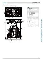
Страница 11: ...ts Legend No Parts name 1 Compressor 2 Discharge temperature switch 3 High pressure switch 4 High pressure sensor 5 Oil separator 6 Four way valve 7 Heat exchanger 8 Electronic expansion valve EXV 9 L...

Страница 12: ...rts name 1 Compressor 2 Discharge temperature switch 3 High pressure switch 4 High pressure sensor 5 Oil separator 6 Four way valve 7 Heat exchanger 8 Electronic expansion valve EXV 9 Low pressure swi...

Страница 13: ...arts name 1 Compressor 2 Discharge temperature switch 3 High pressure switch 4 High pressure sensor 5 Oil separator 6 Four way valve 7 Heat exchanger 8 Electronic expansion valve EXV 9 Low pressure sw...

Страница 14: ...d No Parts name 1 Compressor 2 Discharge temperature switch 3 High pressure switch 4 High pressure sensor 5 Oil separator 6 Four way valve 7 Heat exchanger 8 Electronic expansion valve EXV 9 Low press...

Страница 15: ...mpressor 2 Discharge temperature switch 3 High pressure switch 4 High pressure sensor 5 Oil separator 6 Four way valve 7 Heat exchanger 8 Electronic expansion valve EXV 9 Low pressure switch 10 Fan mo...

Страница 16: ...name 1 Compressor 2 Discharge temperature switch 3 High pressure switch 4 High pressure sensor 5 Oil separator 6 Four way valve 7 Heat exchanger 8 Electronic expansion valve EXV 9 Low pressure switch...

Страница 17: ...exchanger inlet temperature sensor 6 Four way valve T6B Plate heat exchanger outlet temperature sensor 7 Heat exchanger T7C1 Compressor A discharge temperature sensor 8 Electronic expansion valve EXV...

Страница 18: ...rature sensor 6 Four way valve T6B Plate heat exchanger outlet temperature sensor 7 Heat exchanger T7C1 Compressor A discharge temperature sensor 8 Electronic expansion valve EXV T7C2 Compressor B dis...

Страница 19: ...mperature sensor 6 Four way valve T7C1 Compressor A discharge temperature sensor 7 Heat exchanger T7C2 Compressor B discharge temperature sensor 8 Electronic expansion valve EXV SV4 Oil return valve 9...

Страница 20: ...re sensor 6 Four way valve T7C1 Compressor A discharge temperature sensor 7 Heat exchanger T7C2 Compressor B discharge temperature sensor 8 Electronic expansion valve EXV SV4 Oil return valve 9 Low pr...

Страница 21: ...mpressor A discharge temperature sensor 7 Heat exchanger T7C2 Compressor B discharge temperature sensor 8 Electronic expansion valve EXV SV4 Oil return valve 9 Low pressure switch SV5 Fast defrosting...

Страница 22: ...n the defrosting process In cooling mode SV5 opens when outdoor ambient temperature is above 40o C or compressor frequency is below 41Hz 7 Solenoid valve SV6 Allows refrigerant to bypass the expansion...

Страница 23: ...operation Filter Normal control Filter Filter Normal control Filter Filter High temperature high pressure gas High temperature high pressure liquid Medium temperature medium pressure gas Low temperatu...

Страница 24: ...3 T4 T6B T7C1 T7C2 T6A SV8A SV4 SV5 SV6 480 steps Filter Filter 480 steps Unit on Thermostat off Unit on Thermostat on Unit on Thermostat on Unit off Filter Indoor unit operation Filter 480 steps Filt...

Страница 25: ...8 SV6 Closed Filter Filter Closed Unit on Thermostat off Unit on Thermostat on Unit on Thermostat on Unit off Filter Indoor unit operation Filter Normal control Filter Filter Normal control Filter Fi...

Страница 26: ...S C T3 T4 T6B T7C1 T7C2 T6A SV8A SV4 SV5 480 steps Filter Filter 480 steps Unit on Thermostat off Unit on Thermostat on Unit on Thermostat on Unit off Filter Indoor unit operation Filter 480 steps Fil...

Страница 27: ...osed Filter Filter Closed Unit on Thermostat off Unit on Thermostat on Unit on Thermostat on Unit off Filter Indoor unit operation Filter Normal control Filter Filter Normal control Filter Filter Fan...

Страница 28: ...lter Fan off Fan off Fan off Fan off 7 1 1 15 9 3 4 5 6 11 11 10 10 8 13 EXVA E S C T3 T4 2 T7C1 T7C2 SV9 SV4 SV5 SV6 2 High temperature high pressure gas High temperature high pressure liquid Medium...

Страница 29: ...Closed Filter Filter Closed Unit on Thermostat off Unit on Thermostat on Unit on Thermostat on Unit off Filter Indoor unit operation Filter Normal control Filter Filter Normal control Filter Filter F...

Страница 30: ...an off 15 15 7 1 1 12 9 3 4 5 6 11 11 10 10 14 8 8 13 EXVA EXVC E S C T3 T4 2 T7C1 T7C2 T6B T6A SV8A SV8B SV9 SV4 SV5 SV6 2 High temperature high pressure gas High temperature high pressure liquid Med...

Страница 31: ...Filter Filter Closed Unit on Thermostat off Unit on Thermostat on Unit on Thermostat on Unit off Filter Indoor unit operation Filter Normal control Filter Filter Normal control Filter Filter Fan on F...

Страница 32: ...f 15 15 7 1 1 12 3 4 5 6 11 11 10 10 14 8 8 13 EXVA EXVC E S C T3 T4 2 T7C1 T7C2 T6B T6A SV8A SV8B SV9 SV4 SV5 SV6 2 High temperature high pressure gas High temperature high pressure liquid Medium tem...

Страница 33: ...V6 i VRF 50 60Hz 32 Midea V6 i Series Service Manual...

Страница 34: ...60Hz 33 Part 3 Control Part 3 Control 1 General Control Scheme Flowchart 34 2 Stop Operation 35 3 Standby Control 35 4 Startup Control 36 5 Normal Operation Control 38 6 Protection Control 43 7 Specia...

Страница 35: ...on Abnormal shutdown System stops A unit stops when the load demanded decreases 2 Standby control Crankcase heater control 3 Startup control Compressor startup delay control Startup control for coolin...

Страница 36: ...opped The crankcase heater is controlled according to outdoor ambient temperature and discharge temperature When the outdoor ambient temperature is above 40 C the crankcase heater is off when the outd...

Страница 37: ...uently Pc checked every 10 seconds Pc 2 7MPa 1 step increase Pc 2 1MPa 1 step decrease DC fan motor B FANB Electronic expansion valve A EXVA Position steps from 0 fully closed to 480 or 3000 fully ope...

Страница 38: ...olled according to discharge superheat Electronic expansion valve C EXVC Position steps from 0 fully closed to 480 fully open controlled according to temperature different between plate heat exchanger...

Страница 39: ...erent between plate heat exchanger inlet and outlet Four way valve ST1 On Solenoid valve oil balance SV4 Open regularly Solenoid valve fast defrosting in cooling and unloading in heating SV5 Controlle...

Страница 40: ...cording to temperature different between plate heat exchanger inlet and outlet Four way valve ST1 On Solenoid valve oil balance SV4 Open regularly Solenoid valve fast defrosting in cooling and unloadi...

Страница 41: ...ccording to the nominal capacity of indoor units currently running and the indoor unit heat exchanger temperatures 5 3 Compressor Step Control The running speed of the compressors in rotations per sec...

Страница 42: ...the outdoor unit is in standby EXVC is fully closed When the outdoor unit is running EXVC is controlled according to temperature different between plate heat exchanger inlet and outlet 5 6 Outdoor Fan...

Страница 43: ...1050 1050 830 830 31 880 1080 1080 850 850 32 920 1120 1120 870 870 33 920 1140 1140 890 890 34 920 1140 1140 920 920 35 920 1140 1140 920 920 36 ESP 40Pa mode 950 1200 1200 950 950 37 ESP 60Pa mode...

Страница 44: ...peratures and transient spikes in temperature It is performed for each compressor Figure 3 6 3 Discharge temperature protection control When the discharge temperature rises above 120 C the system disp...

Страница 45: ...es above 25 C heating mode is disabled to prevent the mechanical load on compressors becoming too high and to prevent low compression ratios which can result in insufficient compressor internal oil lu...

Страница 46: ...COMP A Fixed frequency Inverter compressor B COMP B DC fan motor A FANA Fan speed controlled according to discharge pressure DC fan motor B FANB Electronic expansion valve A EXVA Position 480 steps or...

Страница 47: ...eps or 3000 steps Electronic expansion valve C EXVC Position 96 steps Four way valve ST1 Off Solenoid valve oil balance SV4 Normal control Solenoid valve fast defrosting SV5 On Solenoid valve EXV bypa...

Страница 48: ...COMP A Fixed frequency Inverter compressor B COMP B DC fan motor A FANA Off DC fan motor B FANB Electronic expansion valve A EXVA Position 480 steps or 3000 steps Electronic expansion valve C EXVC Po...

Страница 49: ...V6 i VRF 50 60Hz 48 Midea V6 i Series Service Manual...

Страница 50: ...V6 i VRF 50 60Hz 49 Part 4 Field Settings Part 4 Field Settings 1 Outdoor Unit Field Settings 50...

Страница 51: ...tandard static pressure default Low static pressure mode reserved Medium static pressure mode reserved High static pressure mode reserved Super high static pressure mode reserved S5 Priority mode 2 Au...

Страница 52: ...NC3 indicate 16 25 indoor units A F on ENC3 indicate 26 31 indoor units The number of indoor units is in the range 32 47 0 9 on ENC3 indicate 32 41 indoor units A F on ENC3 indicate 42 47 indoor units...

Страница 53: ...rity mode control 1 1 Heating priority mode a During cooling operation If an indoor unit requests heating the outdoor unit stops and then restarts in heating mode after 5 minutes Indoor units requesti...

Страница 54: ...ate in heating mode Indoor units requesting cooling or in fan only mode display the mode conflict error 5 Cooling only mode The outdoor unit only operates in cooling mode Indoor units requesting cooli...

Страница 55: ...requency 1 2 2 3 Maximum fan speed and capacity output control in different silent mode Table 4 1 4 Maximum fan speed and capacity output control in different silent mode ENC4 Switch positions Descrip...

Страница 56: ...rt 5 Electrical Components and Wiring Diagrams Part 5 Electrical Components and Wiring Diagrams 1 Outdoor Unit Electric Control Box Layout 56 2 Outdoor Unit Main PCB 58 3 Compressor Inverter Module 65...

Страница 57: ...18HP Figure 5 1 1 8 18HP top layer of electric control box Figure 5 1 2 8 18HP bottom layer of electric control box Power supply terminals Communication terminals block Inductor Filter board Main PCB...

Страница 58: ...5 1 4 20 32HP bottom layer of electric control box Power supply terminals Communication terminals block Inductor Inductor Filter board Main PCB Inverter module Inverter module Reactor Reactor Fan modu...

Страница 59: ...V6 i VRF 50 60Hz 58 Midea V6 i Series Service Manual 2 Outdoor Unit Main PCB 2 1 Ports Figure 5 2 1 Outdoor unit main PCB ports 1 Notes 1 Label descriptions are given in Table 5 2 1...

Страница 60: ...er compressor A and B current sensor connections 0 7 8V AC varying 9 CN16 Reserved 10 CN8 Plate heat exchanger inlet temperature sensor connection 0 5V DC varying 11 CN1 Outdoor ambient temperature se...

Страница 61: ...ponents Function of buttons SW3 to SW6 2 2 2 Table 5 2 2 Function of buttons SW3 to SW6 Button Function SW3 UP In menu mode previous and next buttons for menu modes Not in menu mode previous and next...

Страница 62: ...OK button to enter specified second level menu for example enter n43 mode Menu mode selection flowchart Start Long press SW5 MENU button for 5 seconds Digital display displays n1 Press SW3 SW4 UP DOW...

Страница 63: ...istory error codes n32 Cleaning history error codes n33 Reserved n34 Factory reset n41 Power limitation mode 1 100 capacity output n42 Power limitation mode 2 90 capacity output n43 Power limitation m...

Страница 64: ...to Note 2 8 Outdoor unit actual operating capacity 9 Fan A speed index Refer to Note 3 10 Fan B speed index Refer to Note 3 11 Indoor heat exchanger pipe T2 T2B temperature C Actual value value displ...

Страница 65: ...11 super silent mode 4 7 Static pressure mode 0 standard static pressure 1 low static pressure 2 medium static pressure 3 high static pressure 4 super high static pressure 8 Refrigerant quantity 0 no...

Страница 66: ...ally and flashing if an inverter module error has occurred 1 LED 2 Inverter module error indicator Continuously on if an inverter module error has occurred 1 Note 1 If an inverter module error occurs...

Страница 67: ...Current sensor CN50 BR1 CN31 CN32 Red Red Blue Blue Black Ferrite core N 1 FAN B CN100 N8_1 T6B CN7 EEV CN27 O FAN CN26 O C CN20 O O EEVA T6B CN25 N CN1 CN51 L1 L2 L3 CN2 CN3 CN4 1 O N 2 3 4 CN1 CN4...

Страница 68: ...ent sensor CN100 N8_1 T6B CN7 EEV CN27 O FAN CN26 O C CN20 O O EEVA T6B CN25 N CN1 CN51 L1 L2 L3 CN2 CN3 CN4 C e boa d Main board FAN B 1 O N 2 3 4 CN1 CN4 SW1 w CN41 DC fan drive board A BR2 CN32 CN3...

Страница 69: ...V6 i VRF 50 60Hz 68 Midea V6 i Series Service Manual...

Страница 70: ...V6 i VRF 50 60Hz 69 Part 6 Diagnosis and Troubleshooting Part 6 Diagnosis and Troubleshooting 1 Error Code Table 70 2 Troubleshooting 71 3 Appendix to Part 6 125...

Страница 71: ...ion error Displayed on the unit with the error Refer to Note 3 Yes xH0 Communication error between main control chip and inverter driver chip Displayed on the unit with the error No xH4 Inverter modul...

Страница 72: ...more than 15Hz protection Displayed on the unit with the error Yes Notes 1 x is a placeholder for the compressor system compressor and related electrical components with 1 representing compressor syst...

Страница 73: ...code is displayed on the outdoor unit with the error Trigger recover condition 2 2 3 Trigger condition Wrong phase connection for 1 6s or phase missing for 48s Recover condition Correct phase connect...

Страница 74: ...e requirements If the phase sequence is inverted the compressor will operate inversely If the wiring connection of each outdoor unit is in A B C phase sequence and multiple units are connected the cur...

Страница 75: ...s and the outdoor unit cannot communicate for 2 minutes after the system is powered on for 20 minutes Recover condition Communication go back to normal Reset method Resume automatically Possible cause...

Страница 76: ...rence from high voltage 220V or higher wires Yes Ensure the communication wires and high voltage wires are separated No Communication wires are close to a source of electromagnetic radiation such as t...

Страница 77: ...top running Error code is only displayed on the unit with the error Trigger recover condition 2 4 3 Trigger condition The main control board cannot receive the feedback signal of temperature sensor T3...

Страница 78: ...oor main PCB Notes 1 Outdoor ambient temperature sensor T4 and heat exchanger temperature sensor T3 connection is port CN1 on the main PCB labeled 11 in Figure 5 2 1 in Part 5 2 1 Ports 2 Measure sens...

Страница 79: ...displayed on the unit with the error Trigger recover condition 2 5 3 Trigger condition Outdoor unit power supply phase voltage 165V Recover condition Outdoor unit power supply phase voltage is 180V Re...

Страница 80: ...ce or repair the relevant parts No Replace outdoor main PCB Notes 1 The normal voltage between A and N B and N and C and N is 198 242V 2 The normal resistances of the inverter compressor are 0 7 1 5 a...

Страница 81: ...7C1 2 error All units stop running Error code is only displayed on the unit with the error Trigger recover condition 2 6 3 Trigger condition Discharge pressure 3MPa and discharge temperature 15o C for...

Страница 82: ...B Notes 1 Compressor top temperature sensor and discharge pipe temperature sensor connections are ports CN4 and CN5 on the main PCB labeled 3 and 4 respectively in Figure 5 2 1 in Part 5 2 1 Ports 2 M...

Страница 83: ...it address error All units stop running Error code is only displayed on the unit with the error Trigger recover condition 2 7 3 Trigger condition Outdoor unit address is set more than 3 Recover condit...

Страница 84: ...s and Troubleshooting Procedure 2 7 5 E8 The ODU s address is not in the valid range1 Yes Slave units addresses should be set from 1 to 3 No Replace the outdoor main PCB Notes 1 The V6 Individual outd...

Страница 85: ...essor system B Description 2 8 2 1E9 indicates a compressor A EEPROM mismatch 2E9 indicates a compressor B EEPROM mismatch All units stop running Error code is only displayed on the unit with the erro...

Страница 86: ...y after being powered off1 Yes Power off the unit and wait for the digital display to turn off before restarting the unit No Replace outdoor main PCB Notes 1 When performing a manual restart of an out...

Страница 87: ...DC bus voltage error 2F1 indicates compressor B DC bus voltage error All units stop running Error code is only displayed on the unit with the error Trigger recover condition 2 9 3 Trigger condition D...

Страница 88: ...and end at the N_out terminal on the inverter module Figure 6 2 2 DC detection wire connection method F1 error Compressor inverter module wiring is loosened Reconnect cables based on wiring diagram Re...

Страница 89: ...exchanger cooling refrigerant inlet temperature sensor T6A error All units stop running Error code is only displayed on the unit with the error Trigger recover condition 2 10 3 Trigger condition Temp...

Страница 90: ...ng refrigerant inlet temperature sensor T6A and plate heat exchanger cooling refrigerant outlet temperature sensor T6B connection are port CN8 and CN8_1 on the main PCB labeled 10 and 12 respectively...

Страница 91: ...Trigger recover condition 2 11 3 Trigger condition The main control board cannot receive the feedback signal of EXV Recover condition The main control board can receive the feedback signal of EXV Rese...

Страница 92: ...2 Yes Replace the sensor No Replace outdoor main PCB Notes 1 Electronic expansion valve coil connections are port CN70 CN71 and CN72 on the main PCB labeled 18 19 and 20 respectively in Figure 5 2 1 i...

Страница 93: ...l chip and inverter driver chip cannot communication for 2 minutes Recover condition Communication go back to normal Reset method Resume automatically Possible causes 2 12 4 Incorrect compressor inver...

Страница 94: ...9 Communication port CN26 on main PCB Communication port CN8 CN9 on inverter module 3 LED1 2 on inverter module 4 Check the power supply for the compressor inverter module port CN41 on filter board th...

Страница 95: ...ror Zero speed protection Phase sequence error Excessive compressor frequency variation Actual compressor frequency differs from target frequency Specific error codes for xH4 inverter module protectio...

Страница 96: ...2 4 LED indicators LED1 and LED2 on inverter module Table 5 3 2 Errors indicated on LED1 LED1 flashing pattern Corresponding error Flashes 8 times and stops for 1 second then repeats xL0 Inverter modu...

Страница 97: ...incorrectly Reconnect the cables based on wiring diagram Replace the compressor The inverter module is not well heat dissipation The IPMscrews is loosen Fasten IPM screws again The silica gel is coate...

Страница 98: ...should be 450 650V When the voltage is lower than 350V L1 protection will be appeared Figure 6 2 6 Inverter module terminals L1 protection The power supply is abnormal Check the power supply equipment...

Страница 99: ...and N on inverter module should be 450 650V When the voltage is higher than 700V L2 protection will be appeared Figure 6 2 7 Inverter module terminals L2 protection The power supply is abnormal Check...

Страница 100: ...et of ODU ODU stop valves are closed Open the ODU stop valves Reconnect the cables based on wiring diagram The resistance between 3 phases of compressor is over 5 Replace the compressor The insulation...

Страница 101: ...e sequence error 2 13 10 L7 protection Compressor wiring is loose Reconnect cables based on wiring diagram An open circuit in the 3 phase U V W of compressor terminals Replace the compressor Replace t...

Страница 102: ...t the cables based on wiring diagram The resistance between 3 phases of compressor is over 5 Replace the compressor The insulation resistance of compressor is less than 100 Replace the compressor inve...

Страница 103: ...the system Drain the oil from any compressors where the oil has been spoiled Go to Step 4 Step 4 Replace oil separator s and accumulator s If the oil from a compressor is spoiled lightly or heavily d...

Страница 104: ...arge refrigerant Refer to the V6 Engineering Data Book Part 3 Figure 6 2 10 Inspecting compressor oil This oil is black it has been carbonized This oil is a little yellow but is clear and transparent...

Страница 105: ...ce Manual Figure 6 2 11 Effects of spoiled compressor oil Worn scroll plate Worn scroll plate Normal compressor bearings Seriously worn and damaged bearings Filter blocked by impurities which leads to...

Страница 106: ...ot be detected by the outdoor unit for 8 hours or more than one indoor unit cannot be detected by the outdoor unit for 3 minutes Recover condition Number of indoor units detected by the outdoor unit i...

Страница 107: ...the indoor unit error resolves the outdoor unit error No Two or more indoor units are assigned the same address3 No Yes Setting the indoor units addresses uniquely resolves the error No Replace outdoo...

Страница 108: ...displayed on the unit with the error Trigger recover condition 2 15 3 Trigger condition Discharge pressure 0 3MPa Recover condition Discharge pressure 0 3MPa Reset method Resume automatically Possibl...

Страница 109: ...essure sensor If the resistance is of the order of mega Ohms or infinite the pressure sensor has failed 3 An insufficiency of refrigerant causes compressor discharge temperature to be higher than norm...

Страница 110: ...h the error Trigger recover condition 2 16 3 Trigger condition Discharge pressure 4 4MPa Recover condition Discharge pressure 3 2MPa Reset method Resume automatically Possible causes 2 16 4 Outdoor un...

Страница 111: ...rge temperature to be lower than normal discharge pressure to be higher than normal and suction pressure to be higher than normal For normal system parameters refer to Table 6 3 4 and 6 3 5 in Part 6...

Страница 112: ...ill disappear once the system reaches a steady state All units stop running Error code is only displayed on the unit with the error Trigger recover condition 2 17 3 Trigger condition For P2 protection...

Страница 113: ...pressures to be lower than normal and compressor current to be lower than normal and may cause frosting to occur on the suction pipe These issues disappear once sufficient refrigerant has been charge...

Страница 114: ...DC80PHDG D1YG 33A Recover condition Current of compressor AA55PHDG D1YG 24 6A or DC80PHDG D1YG 33A Reset method Resume automatically Possible causes 2 18 4 Outdoor unit stop valves are closed Indoor...

Страница 115: ...parameters refer to Table 6 3 4 and 6 3 5 in Part 6 3 2 Normal Operating Parameters of Refrigerant System 3 Air or nitrogen in the system causes discharge temperature to be higher than normal discharg...

Страница 116: ...estart Possible causes 2 19 4 Outdoor unit stop valves are closed Temperature sensor switch not connected properly or has malfunctioned Insufficient refrigerant System blockage Indoor load too large S...

Страница 117: ...discharge temperature to be higher than normal discharge and suction pressures to be lower than normal and compressor current to be lower than normal and may cause frosting to occur on the suction pi...

Страница 118: ...e unit with the error Trigger recover condition 2 20 3 Trigger condition Outdoor heat exchanger temperature T3 65o C Recover condition Outdoor heat exchanger temperature T3 55 o C Reset method Resume...

Страница 119: ...e resistance is not consistent with the sensor s resistance characteristics table the sensor has failed Refer to Table 6 3 1 in Part 6 3 1 Temperature Sensor Resistance Characteristics 3 An indoor loa...

Страница 120: ...restart Possible causes 2 21 4 Switch ENC2 incorrectly set Power or communication wires not connected properly Fan motor blocked or has failed Power supply abnormal AC filter board damaged Fan module...

Страница 121: ...abnormal Yes Check the power supply equipment No Voltage between P and N on fan module is abnormal1 Yes Replace AC filter board No Replacing the fan module resolves the error No Replace outdoor main P...

Страница 122: ...nverter module B temperature protection All units stop running Error code is only displayed on the unit with the error Trigger recover condition 2 22 3 Trigger condition For PL protection Inverter mod...

Страница 123: ...he sensor is connected properly No Inverter module temperature sensor has short circuited or failed2 Yes Replace the sensor No Replace outdoor main PCB Notes 1 Inverter module temperature sensor conne...

Страница 124: ...e is only displayed on the unit with the error Trigger recover condition 2 23 3 Trigger condition Discharge gas superheat is 0o C for 20 minutes or 5o C for 60 minutes Recover condition Discharge gas...

Страница 125: ...harge pressure is too high Yes Troubleshoot as for a P1 error4 No Replace outdoor main PCB Notes 1 Compressor top temperature sensor and discharge pipe temperature sensor connections are ports CN4 and...

Страница 126: ...112 0 4470 7 52 24 33 6 981 73 1 485 113 0 4348 6 49 32 34 6 684 74 1 435 114 0 4230 5 46 57 35 6 400 75 1 387 115 0 4116 4 44 00 36 6 131 76 1 341 116 0 4006 3 41 59 37 5 874 77 1 291 117 0 3899 2 3...

Страница 127: ...9 32 40 57 72 8 940 112 2 630 7 261 4 33 38 89 73 8 643 113 2 559 6 247 8 34 37 30 74 8 358 114 2 489 5 234 9 35 35 78 75 8 084 115 2 422 4 222 8 36 34 32 76 7 820 116 2 357 3 211 4 37 32 94 77 7 566...

Страница 128: ...75 63 12 22 103 3 418 16 423 0 24 57 17 64 11 79 104 3 326 15 399 8 25 54 71 65 11 39 105 3 235 14 378 0 26 52 36 66 10 99 106 3 148 13 357 5 27 50 13 67 10 62 107 3 063 12 338 2 28 48 01 68 10 25 10...

Страница 129: ...s low the system is being run in heating mode with the following settings temperature 30 C fan speed high The system has been running normally for more than 30 minutes Table 6 3 4 Outdoor unit cooling...

Страница 130: ...ong China Postal code 528311 Tel 86 757 26338346 Fax 86 757 22390205 cac midea com global midea com Note Product specifications change from time to time as product improvements and developments are re...

Отзывы: