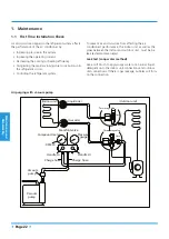


Maintenance and
Disassembly
Page 36
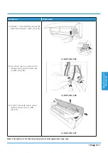
2. Electrical parts
Note: Remove the front panel (refer to 1. Front panel) before disassembling electrical parts.
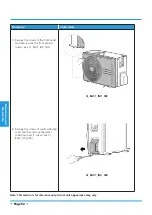
Procedure
Illustration
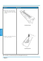
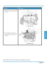
1) Cut the ribbon by a shear, then pull
out the coil temperature sensor (T2)
(see CJ_MB1_INV_017).
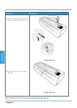
2) Remove one fixing screw of the
electronic control box and two screws
used for the ground connection (see
CJ_MB1_INV_017).
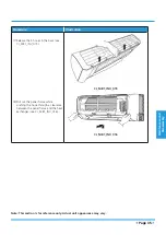
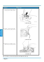
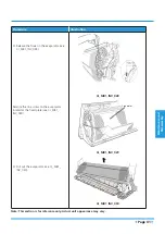
3) An upward force is maintained until
the cover of electronic control box is
removed (see CJ_MB1_INV_018).
CJ_MB1_INV_017
CJ_MB1_INV_018
Note: This section is for reference only. Actual unit appearance may vary.
Ribbon
T2 Sensor
Ground Screws
Содержание MISSION2 3D INVERTER Series
Страница 1: ...MISSION2 3D INVERTER SERIES SM_MISSION2 GA _60R410A_3D INVERTER_US_NA_171121 2017 SERVICE MANUAL...
Страница 2: ......
Страница 4: ......
Страница 11: ...Specifications Page 7 MOB01 09HFN1 MW0W MOB01 12HFN1 MV0W MOCA01 18HFN1 MT0W...
Страница 12: ...Specifications Page 8 MOD01 23HFN1 MT0W...
Страница 15: ...Specifications Page 11 PCB board of MOD01 23HFN1 MT0W...
Страница 16: ...Specifications Page 12 IPM board of MOD01 23HFN1 MT0W...
Страница 101: ...Troubleshooting Page 97 Remark Measure the DC voltage between P and N port The normal value should be around 310V...


