


Tr
oubleshooting
Page 96
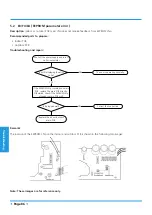
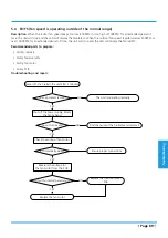
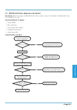
5.10 P1(Over voltage or too low voltage protection diagnosis and solution)
Description:
Abnormal increases or decreases in voltage are detected by checking the specified voltage detection circuit.
Recommended parts to prepare:
• Power supply issues
• System leakage or blockage
• Faulty PCB
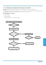
Troubleshooting and repair:
Check the power supply.
Is it in working order?
Turn off the unit.
NO
Check the connections and wires.
YES
Are they in working order?
Ensure proper connections or
replace the wires.
NO
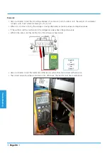
Power on and measure the
voltage between P and N.
YES
While the unit is in standby,
is the voltage between P and N is around
DC 310V, 340V or 380V? When start up
the unit, is it in 220V~400V?
Replace the IPM board.
NO
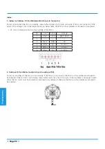
Check the reactor.
YES
Is it in working order?
Replace outdoor PCB.
NO
Replace the reactor.
YES
Содержание MISSION2 3D INVERTER Series
Страница 1: ...MISSION2 3D INVERTER SERIES SM_MISSION2 GA _60R410A_3D INVERTER_US_NA_171121 2017 SERVICE MANUAL...
Страница 2: ......
Страница 4: ......
Страница 11: ...Specifications Page 7 MOB01 09HFN1 MW0W MOB01 12HFN1 MV0W MOCA01 18HFN1 MT0W...
Страница 12: ...Specifications Page 8 MOD01 23HFN1 MT0W...
Страница 15: ...Specifications Page 11 PCB board of MOD01 23HFN1 MT0W...
Страница 16: ...Specifications Page 12 IPM board of MOD01 23HFN1 MT0W...
Страница 101: ...Troubleshooting Page 97 Remark Measure the DC voltage between P and N port The normal value should be around 310V...


