DX-2200
– SD/HD-SDI Text & Graphics Inserter – User Manual
Page 59 of 103
4.8.1.12.3 E
NABLING AND
D
ISABLING
L
AYERS
If one or more layers are not required in an application, they can be disabled using the LnnnH command.
Layers that have been disabled can be re-enabled using the LnnnA command. In some circumstances,
disabling layers that are not used can improve update performance on the remaining layers.
These commands are relatively slow and may disturb the output video. They are recommended for use
during initial setup or at times when clean video output is not required.
4.8.1.12.4 R
E
-S
IZING
O
VERLAYS
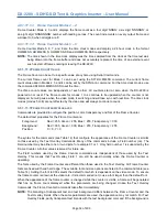
By default, all overlay layers are the same size as the video output of the DX-2200-TI. The LnnnKxxxx,yyyy
command sets a preferred size for the overlay. If the preferred size is smaller than the video size, the
overlay is reduced in size to match the preferred size. The overlay will never be larger than the output video
size.
When the overlay size is changed, the layer will be disabled momentarily and both the active and spare
frame buffers will be cleared. To see the content of the overlay after a size change the layer must be
updated, for example using the LnU command.
Setting xxxx and/or yyyy to 0 restores the default overlay size. It is not possible to set the overlay width or
height smaller than 16 pixels. For any of the interlaced video modes, the height of the overlay must be an
even number of pixels and will be automatically rounded up if necessary.
4.8.1.12.5 M
OVING
A
N
O
VERLAY
When an Overlay has been reduced in size, (via the LnnnKxxxx,yyyy command) it is then possible to change
the x, y position of the overlay item within the boundaries of the output video. This process can then be used
for moving/panning an OSD target marker around the displayed video.
The LnnnPxxxx,yyyy sets the x and y position of the overlay. The overlay must always fit completely within
the boundaries of the output video. It is not possible to have an overlay partially off screen. This is the
reason that the overlay must be reduced in size before the position can be changed. It is also possible to
change only the x position using the LnnnPXxxxx command, or only the y position using the LnnnPYyyyy
command.
By default, the overlay position coordinates refer to where the top-left corner of the overlay is located in the
output video. The reference point can be changed to the center of the overlay instead of the top left corner
using the LnnnPM2 command.
Moving the overlay is very fast because it does not require rendering any Fields or switching the overlay
buffers. The overlay item can be repositioned at the video frame rate by sending Serial Commands at an
appropriate interval.
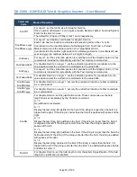
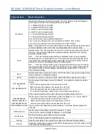
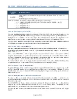
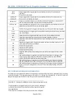
Table 15: Layer Control SERIAL Command Codes
Command
Code
Mode of Operation
Layer Control Commands
LnnnU
Update layer nnn by rendering all Fields on the layer(s) to the spare buffer, then
switching the spare and active buffers to make the update visible.
nnn is the layer number(s), See **
After the buffer switch, the new spare buffer is automatically cleared.
LnnnB
Renders the Text or Graphics Fields on Layer(s) nnn to the spare buffer, but the buffers
are not swapped. The video output does not change.
nnn is the layer number(s), See **
Содержание DX-2200
Страница 87: ...DX 2200 SD HD SDI Text Graphics Inserter User Manual Page 87 of 103 ...
Страница 92: ...DX 2200 SD HD SDI Text Graphics Inserter User Manual Page 92 of 103 ...
Страница 96: ...DX 2200 SD HD SDI Text Graphics Inserter User Manual Page 96 of 103 Figure 31 PuTTY Serial Port Settings ...
Страница 97: ...DX 2200 SD HD SDI Text Graphics Inserter User Manual Page 97 of 103 ...
Страница 100: ......
Страница 101: ......
Страница 102: ......
Страница 103: ......

