background image

DX-2200 

– SD/HD-SDI Text & Graphics Inserter – User Manual 


Page 36 of 103 


4.8.1.9.10.5.1  Corner Marker Field Display Example: 

G1M3 


' corner marker field type 

G1PA100,100 


' top-left at (100,100) 

G1PB1820,980 


' bottom-right at (1820,980) 

G1W10 


' 10 pixels wide 

G1L300,150 


' 300 px long horizontal, 150 px vertical 

G1R255;G1G255;G1B0 


' Yellow 

G1A64 


' 25% transparent 

G1S 


' display and update 

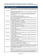
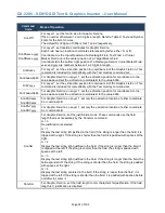
4.8.1.9.10.6 

Target Marker Fields 

– Field Type 4 

The Target Marker Field displays a '+' marker at the position specified by coordinate A of the Graphic Field. 

The Length parameter of the Graphic Field sets the length of the horizontal and vertical lines. Half the length 
extends  each  direction from the center of the Target Marker and the length has a resolution of 2  pixels so 
that the marker is always symmetrical. 

The  width  parameter  of  the  Graphic  Field  set  the  width  of  the  lines  that  make  up  the  Target  Marker.  The 
width has a resolution of 2 pixels with half the width on each side of center. 

4.8.1.9.10.6.1  Target Marker Field Display Example: 

G3M4 


' target marker field type 

G3PA960,540 


' location (960,540) 

G3W2 


' 2 pixels wide 

G3L100 


' 100 pixel long lines 

G3R255;G3G0;G3B0 


' red 

G3A0 


' fully visible 

G3S 


' display and update 


4.8.1.9.10.7 

Image Fields 

– Field Type 5 

An Image Field displays an image that has been uploaded to the DX-2200-TI-03. Image Fields can be used 
to  display  a  logo  or  other  custom  graphics.  The  DX-2200  Uploader  software  supplied  with  the  product  is 
used  to  upload  images  and  store  them  in  flash  memory.  Refer  to 

§5

DX2200  Software  Upload  Utility  DX-

2200 Software Upload Utility for information about uploading images. 

The image is displayed at the position specified by coordinate A of the Graphic Field. Any part of the image 
extending beyond the size of the overlay is not displayed. 

Uploaded  images  may  have  transparency  for  some  or  all  pixels  in  the  image.  Support  for  transparency 
depends on the file format of the image. Images that do not include transparency are always uploaded with 
all  pixels  fully  visible.  By  default,  images  will  be  displayed  with  the  transparency  that  was  included  in  the 
uploaded  image.  The  GnnAaaa  command  can  be  used  to  make  the  image  more  transparent.  It  is  not 
possible to make an image less transparent than was defined in the original file. 

When an image is fully transparent or partly transparent, the image frame background will be visible behind 
the  image.  The  background  color  is  set  by  the  GnnBRrrr,  GnnBggg,  GnnBBbbb  commands,  and  the 
background  transparency  is  set  by  the  GnnBAaaa  command.  When  the  image  frame  background  has 
transparency,  lower  layers  in  the  video  mix  will  be  visible  behind  the  image.  The  default  background 
transparency  for  a  graphic  field  is  255  (fully  transparent).  The  image  frame  background  will  not  be  visible 
unless the default transparency is changed.  

Содержание DX-2200

Страница 1: ...4056 Meadowbrook Drive Unit 126 London ON Canada N6L 1E3 www microtronix com MICROTRONIX DX 2200 SD HD SDI TEXT GRAPHIC INSERTER USER MANUAL VERSION 1 75 ...

Страница 2: ...mages in flash memory and display them on the overlay Fix a problem that caused graphics to be skewed for some overlay sizes July 21 2014 1 21 Add wingdings font table Oct 16 2014 1 23 Add 13 extended UTF8 characters to the Tahoma fonts Nov14 2014 1 31 Fonts and images are loaded on first use to make the DX 2200 start faster Added graphic field type 6 rectangle specified by top left and width heig...

Страница 3: ...July 19 2017 1 67 Add an additional arrow character to the Wingding fonts at code 005F Aug 23 2017 1 68 Added configuration bypass function Nov 13 2017 1 70 Modified the configuration bypass function to also bypass loading of images from flash memory Improve handling of corrupted images in the flash memory Fix a bug in the frame counter when using 1000 1001 frame rates Add a time clock mode to the...

Страница 4: ...er software to customer requirements Contact Microtronix sales sales microtronix com with your requirements Safety Critical Life System Applications Notice to User The Microtronix DX 2200 SDI Video Products are not designed or approved by Microtronix for use in safety critical or life critical system or application in which a failure or malfunction may result in one or more of the following outcom...

Страница 5: ...d 21 4 8 1 7 Picture in Picture Position Size and Zoom SERIAL Commands 22 4 8 1 8 Main Input Scaling and Position SERIAL Commands 25 4 8 1 9 Graphic Overlay SERIAL Commands 27 4 8 1 9 1 Active Layer 27 4 8 1 9 2 Graphic Fields 27 4 8 1 9 3 Reset Graphic Field 28 4 8 1 9 4 Graphic Field Visibility 28 4 8 1 9 5 Update Graphic Overlay 29 4 8 1 9 6 Coordinate System and Field Position 29 4 8 1 9 7 Lin...

Страница 6: ...ce Function Configuration 61 4 8 1 13 3 1 User Interface Commands 62 4 8 1 13 4 Resetting to Factory Default Configuration 62 4 8 1 13 5 Recommendations for Configuration 62 4 8 1 13 6 Example Configuration Command File 63 4 8 1 14 GPS Receiver Support 64 4 8 1 14 1 Connection of the GPS Receiver 64 4 8 1 14 2 GPS Data Capture 66 4 8 1 14 3 Selection of Data Fields the CC command 70 4 8 1 14 4 GPS...

Страница 7: ... 1 JTAG Firmware Upload Procedure 90 A 5 Reset Pushbutton SW1 90 A 6 Board Mechanical Dimensions 90 Appendix B USB to RS 232 Serial Port Adapter 93 B 1 ICUSB232V2 Software Drivers 93 B 1 1 Installation of ICUSB232V2 Serial Driver and Terminal Emulator Program 93 B 2 Establishing Serial Communications 94 Appendix C Regulatory Compliance Information 98 C 1 Industry Canada IC 98 C 2 Federal Communica...

Страница 8: ...AL Commands 47 Table 13 Graphic Layer 1 Low Level Overlay Commands 52 Table 14 Frame Counter Overlay SERIAL Command Codes 56 Table 15 Layer Control SERIAL Command Codes 59 Table 16 User Interface Command Codes 62 Table 17 DB9 Serial Y Splitter Cable Pin Connections 65 Table 18 GPS Data Fields 66 Table 19 Data Formatting for the CC Command 70 Table 20 GPS Interface Setup Command 72 Table 21 Flash S...

Страница 9: ...le of the available Tahoma font sizes 32 Figure 14 Character set codes 20 7F and A0 FF 33 Figure 15 Sample of Rectangle Target Marker and Text 37 Figure 16 Sample of Corner Markers Target and Text 38 Figure 17 Example 1 red text OSD with white background 46 Figure 18 Example 2 sample of default text 47 Figure 19 Frame Counter text display Example 2 55 Figure 20 Frame Counter text display Example 3...

Страница 10: ... video format Ancillary data from the video input is preserved to provide pass through of audio closed captions and other metadata on the main SDI input Text and Graphics Overlay OSD Three overlay layers Up to 48 independent text or graphic Fields per layer Fields support text rectangle corner markers target marker and graphic images Filled or open rectangles Size color transparency and position c...

Страница 11: ...product package includes the following items SD HD SDI Text Graphics Inserter with Loop Output Model PN DX 2200 TI 14 or SD HD SDI Text Graphics Inserter with PIP and Loop Output Model PN DX 2200 TI 24 100 240VAC 12VDC 1 3A Power Adapter PN 589 PS 1213AP USB 2 0 to RS 232 DB9 Serial Adapter Kit PN 8121 USB RS232 KIT User Manual on CD ...

Страница 12: ...s A fail safe buffered SD HD SDI Loop Output is available for passing through the input signal unmodified as may be required for broadcast applications 2 1 Text and Graphics Overlay OSD Features Features of the overlay OSD include 1 Three layers for text and graphics fields 2 Display of 48 independent fields per layer 3 Fields support Text Rectangles Corner Markers Target Marker and Image modes 4 ...

Страница 13: ...oduct supplied in an enclosure as show in Figure 1 and Figure 2 below or optionally as an open frame board for building into embedded video system as shown in Figure 25 shown in Appendix A Figure 1 DX 2200 TI 14 SD HD SDI Text Graphics Inserter with SDI Loop Output Figure 2 DX 2200 TI 24 SD HD SDI Text Graphics Inserter with PIP and SDI Loop Output ...

Страница 14: ... PN 16282 2SG 311 or optionally from a 14 4V Lithium ion brick battery 3 1 1 AC Power Adapter The DX 2200 TI unit has a current draw of 650mA when operating from at 12VDC regulated power source A picture of the AC power adapter is shown in the figure below Figure 3 12Vdc 1 33A 100 240VAC Power Adapter Figure 4 Pin Assignments of 2 pin Power Plug 3 1 2 Example of 14 4VDC Lithium Battery A picture o...

Страница 15: ...e 14 4VDC D TAP adapter cable shown in the figure above can be ordered using Microtronix part number D TAP 2P C 3 2 Environmental Operating Limits The DX 2200 unit uses passive convection cooling based on unrestricted airflow around the unit The environmental operating limits are as follows Ambient Temperature Range 0C to 40C Relative Humidity 0 to 95 non condensing ...

Страница 16: ...will pass the input video through to the output with no text overlay items added The DX 2200 TI will automatically output in the same video format as is detected at the input If there is no input signal or if it cannot be properly detected the SDI output will display black and the video format will be 720p 60 fps A user specific setup can be stored in flash to enable the DX 2200 TI to start in a d...

Страница 17: ... SDI input video is a progressive video format ON The SDI input video is either an interlaced or PsF video format Input Bottom Board D4 Red Valid Video OFF The SDI input has either no video or an unsupported video format ON A signal is detected on the input Output Board D4 Green Power ON Power OK Output Top Board D5 Red Output On OFF SDI output is not enabled ON The SDI output is enabled Output Bo...

Страница 18: ...n frame rate If the main input is an interlaced format the PiP input must be interlaced and if the main input is a progressive format the PiP input must be progressive The size and position of the PiP is programmable by software commands The PiP input will only function after the background video has been connected to Input 1 The PiP input does not support audio or other ancillary data types For i...

Страница 19: ... and the layer order When a field is fully visible no content that is on the layers below it will be visible When the field is partly or fully transparent it mixes with the layers below according to their transparencies 4 8 SERIAL MANUAL Control The SD HD SDI Video Text Inserter has two methods of control SERIAL Control using the RS232 port and MANUAL Control using the DIP switch and Toggle switch...

Страница 20: ...ollowing a tick character are treated as comments A comment may begin after a delimiter or may follow a command with or without spaces or tabs between the command and the comment ASCII string parameters are delimited with quotation marks If a quotation mark or backslash character is required within a string for example to display as part of a text overlay then it must be preceded by a backslash ch...

Страница 21: ...Ancillary Data SERIAL Commands By default the DX 2200 TI preserves all ancillary data in the video signal It is possible to control this function if the ancillary data is not required Disabling the ancillary data may slightly increase graphic update speed in some situations Table 6 Ancillary Data Control SERIAL Command Codes Command Code Mode of Operation MA0 Disable ancillary data pass through MA...

Страница 22: ...s in the example The second method of setting PiP size and position does not use predefined sizes or positions instead the width height and the x and y position of the top left corner are set in terms of number of pixels by using the commands PWxxxx PHyyyy PXxxxx PYyyyy followed by either PU or PR to apply the settings For example PiP configured using method 2 PX100 Set Top Left corner of PiP to x...

Страница 23: ...the predefined PiP positions Enter the value 9999 to use the default PByyyy Set the vertical gap in pixels between the reference corner and the Pip window when using the predefined PiP positions Enter the value 9999 to use the default PU PiP update sets PiP size and position to values selected with W H X and Y commands PR PiP update fixed aspect ratio sets PiP size and position to values selected ...

Страница 24: ...ues to a valid range The default setting is 50 for both horizontal and vertical meaning the PiP is zoomed in toward its center These commands only has an effect in center zoom control mode See the ZPF command ZPnnn d Set the zoom factor as a percentage from 100 0 to 800 0 with up to one optional decimal place The default is 100 no zoom This command only has an effect in the center zoom control mod...

Страница 25: ...Scaling Mode Mode 3 provides the graphic overlay functions and two additional capabilities 1 The option to zoom in on a selected region of the video source to allow cropping or display of a selected rectangular region of the source 2 The video source can be mixed into the output as a reduced size window instead of filling the output video frame This function is controlled by the Output Window Size...

Страница 26: ...he width to maintain the aspect ratio The DX 2200 will always limit the window size to prevent it being larger than the video frame BR Reset size and position to defaults Where nnnn can be a number of pixels between one and four digits in length or be followed by a sign to specify a percentage of the output frame size eg 50 When specified in the value can be an integer between 0 to 100 Table 8 Tex...

Страница 27: ... amount of time required to render the text to the spare buffer depends on the number of pixels that must be drawn Typically the rendering process takes more than one frame to complete During this time the active buffer continues to provide the Graphic Overlay video output After rendering is complete the DX 2200 TI switches the active and spare buffers The buffer that was active before the update ...

Страница 28: ...mmand resets the fields on all layers to default Resetting a Graphic Field will clear the Text string set the line color to white with full visibility set the position to the top left corner set the fill color to blue but fully transparent not visible and set the font to the default for the current video resolution The overall visibility of the Field is set to off Resetting fields does not automat...

Страница 29: ... and y 575 NOTE Some monitors will not display the entire video frame particularly when operating in NTSC or PAL modes Graphic Fields placed close to the edges of the overlay may not be visible on some monitors NOTE If the Overlay has been re sized the coordinate range may be smaller than the defaults for each video mode listed above Any Field or portion of a Field that extends beyond the edges of...

Страница 30: ...lly transparent At this setting the color will be completely invisible For example sending G1A192 makes Field 1 approximately 75 transparent Changing the text transparency does not automatically update the video output 4 8 1 9 8 BACKGROUND COLOR AND TRANSPARENCY Each Field has a Background Color that is used for the background of Text Fields and the fill color of rectangles Background Color is set...

Страница 31: ... A0 FF 18 Tahoma Regular 32 20 7E A0 FF 19 Tahoma Regular 40 20 7E A0 FF 24 Tahoma Bold 48 20 7E A0 FF 20 Tahoma Regular 60 20 7E A0 FF 21 Tahoma Regular 78 20 7E A0 FF 22 Tahoma Regular 116 20 7E A0 FF 23 Tahoma Regular 156 20 7E A0 FF 26 Vera Sans Mono Regular 18 20 7E A0 FF 27 Vera Sans Mono Regular 26 20 7E A0 FF 28 Vera Sans Mono Regular 32 20 7E A0 FF 29 Vera Sans Mono Regular 40 20 7E A0 FF...

Страница 32: ... codes Fonts are loaded into memory individually the first time a layer update is performed that requires them The requirement to load the font makes the first layer update significantly slower Selecting font 0 uses a default font that varies depending on the video output resolution For NTSC PAL and 720p the default font is Font 1 and for 1080i and 1080p the default is Font 2 If the font has been ...

Страница 33: ...isplayed are enclosed in the quotation marks If a quotation mark is required in the test it must be preceded by the backslash character For example to set the text string for Field 7 to display Model DX 2200 TI use the command G07T Model DX 2200 TI The color and transparency of the character can be configured using GnnRrrr GnnGggg GnnBbbb to set the red green and blue component of the character co...

Страница 34: ...horizontal line widths xxxx and vertical widths yyyy independently When the Width parameter is set to 0 in the above commands or when the Width is greater than half the size of the rectangle the entire rectangle is drawn with the line color The line width can also be set for each side of the rectangle individually The commands GnnWLwwww GnnWRwwww GnnWTwwww and GnnWBwwww set the width of the left r...

Страница 35: ...lds Field Type 3 Corner Marker Fields are used to indicate a region of interest in the video The Corner Markers are drawn outside the region specified by Coordinate A top left and Coordinate B bottom right The Width parameter of the Graphic Field sets the width in pixels of the lines that make up the corner markers and the Length parameter of the Graphic Field sets the distance in pixels that the ...

Страница 36: ...TI 03 Image Fields can be used to display a logo or other custom graphics The DX 2200 Uploader software supplied with the product is used to upload images and store them in flash memory Refer to 5DX2200 Software Upload Utility DX 2200 Software Upload Utility for information about uploading images The image is displayed at the position specified by coordinate A of the Graphic Field Any part of the ...

Страница 37: ...ploaded transparency G5S display the field and update the overlay 4 8 1 9 10 8 Rectangle XYWH Field Type 6 This rectangle field type is the same as field type 2 with the exception that it is specified by top left corner and width height instead of top left corner and bottom right corner In some applications it may be more convenient or efficient to specify the rectangle with width and height The G...

Страница 38: ... the next update of that GZ Reset all Graphic Fields on the active layer to default This command only resets the parameters of the Fields but does not update the layer The video will not change until the layer is updated GnnZ Reset Graphic Field nn of the active layer to defaults The layer is not automatically updated and the video will not change until the next update GnnMm Select the type for Gr...

Страница 39: ...s used for text background and for the fill region of a rectangle GnnBGggg For Graphic Field nn on the active graphics layer set the value of the green component of the background color to ggg where ggg is a number between 1 and 3 digits in length and in the range 0 to 255 The background color is used for text background and for the fill region of a rectangle GnnBBbbb For Graphic Field nn on the a...

Страница 40: ...d bottom horizontal lines of a rectangle wwww is a number between 1 and 4 digits in length A width of zero means there is no fill associated with the top and bottom lines GnnFYwwww For Graphic Field nn on the active graphics layer set the fill width in pixels associated with the left and right vertical lines of a rectangle wwww is a number between 1 and 4 digits in length A width of zero means the...

Страница 41: ...sed Note This command has no effect for corner marker or target fields GnnWRwwww For field nn on the active graphics set the Line width of the right side of a rectangle to the value wwww wwww is a number between 1 and 4 digits in length A width of zero causes the right line to be suppressed Note This command has no effect for corner marker or target fields GnnWTwwww For field nn on the active grap...

Страница 42: ...ion coordinates for Graphic Field nn Each Field has two location coordinates referenced by letter either A or B Coordinate A is the top left position of a Rectangle Field Text Field or Corner Marker Field and is the center position of a Target Marker Field Coordinate B is the bottom right position of a Rectangle Field or Corner Marker Field xxxx and yyyy are numbers between 1 a 4 digits in length ...

Страница 43: ...tification is disabled 4 8 1 9 11LOW LEVEL GRAPHIC COMMANDS The Low Level Graphic Commands provide an additional level of control over switching between the active and spare overlay buffers and in rendering Graphic Fields In certain situations the use of these commands can provide fast update rates for the Overlay The Graphics Overlays of the DX 2200 TI 03 use two memory frame buffers One of these...

Страница 44: ...s must be done prior to the desired switching time so that there is time to render to the spare buffer The spare buffer now contains the updated output but it not yet being displayed When the update is to be displayed execute the GW command and the buffers will be switched at the end of the current frame to make the update visible 4 8 1 9 11 2 Application Example 2 Suppose that 5 text fields are b...

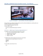
Страница 45: ...00 select Graphics Layer 1 and set the text string for Graphic Field 3 The command S3T DX 2200 performs the same function without changing the Active Layer Refer to Table 12 Graphic Layer 1 Overlay Serial Commands and Table 13 Graphic Layer 1 Low Level Overlay Commands for more details 4 8 1 10 1SAMPLE GRAPHIC LAYER 1 OVERLAY COMMANDS 4 8 1 10 1 1 Graphic Layer 1 Overlay Commands Example 1 Display...

Страница 46: ...eld 1 The command would be S1T This is an updated text string for Text Field 1 SU 4 8 1 10 1 2 Graphic Layer 1 Overlay Commands Example 2 The addition of a second text field with the default font and color Text A text sample using default values for Text Field 2 Default text size at 720p 002 Position X 0600 Y 0200 Default color white The SERIAL Commands to display this text as Field 2 are as follo...

Страница 47: ... 1 Text default m 2 Rectangle m 3 Corner Markers m 4 Target Marker m 5 Graphic Image m 6 Rectangle specified by top left corner and width height SU Update Layer 1 The Graphic Fields on the active layer are rendered to the spare frame buffer and when rendering is complete the frame buffers are switched so that the spare buffer becomes active and the updated video is displayed The new spare buffer i...

Страница 48: ... nn on Layer 1 set the value of the blue component of the background color to bbb where bbb is a number between 1 and 3 digits in length and in the range 0 to 255 The background color is used for text background and for the fill region of a rectangle SnnBAaaa For Graphic Field nn on Layer 1 set the value of the transparency for the background to aaa where aaa is a number between 1 and 3 digits in ...

Страница 49: ...ber between 1 and 4 digits in length A width of zero means there is no fill associated with the left line SnnFRwwww For Graphic Field nn on Layer 1 set the fill width in pixels associated with the right line of a rectangle wwww is a number between 1 and 4 digits in length A width of zero means there is no fill associated with the right line SnnFTwwww For Graphic Field nn on Layer 1 set the fill wi...

Страница 50: ...n length A width of zero causes the bottom line to be suppressed Note This command has no effect for corner marker or target fields SnnLxxxx yyyy Set the Length parameter of Graphic Field nn to the value xxxx for the x direction and to the value yyyy for the y direction xxxx and yyyy are numbers between 1 and 4 digits in length For Corner Markers Length is the distance in pixels each marker extend...

Страница 51: ...on Layer 1 set the x direction position for coordinate A to the value aaaa and set the x direction coordinate B to the value bbbb SnnPAXxxxx SnnPBXxxxx For Graphic Field nn on Layer 1 set only the x direction location of either coordinate A or coordinate B SnnPAYyyyy SnnPBYyyyy For Graphic Field nn on Layer 1 set only the y direction location of either coordinate A or coordinate B SnnNm For Graphi...

Страница 52: ...rame number It can also display the time from a clock that is independent of the video formatted as HH MM SS with 0 to 3 decimal places for seconds The DX 2200 does not have a battery backed up real time clock therefore the time and frame counts are lost when the unit is powered down or reset If the frame count needs to be set to real time or some other specific starting value then an external con...

Страница 53: ...figure the position color transparency and font of the Frame Counter The default text properties for the Frame Counter are Foreground Red 255 Green 255 Blue 255 Transparency 000 Background Red 000 Green 000 Blue 255 Transparency 255 Position X 0 Y 0 The syntax for the commands see Table 14 that configure the appearance of the Frame Counter is similar to those used by the Text Overlay Commands Many...

Страница 54: ...t has been by displayed using the Frame Counter in Manual mode will not be restored when the unit powers up Only text fields displayed using the Text Overlay Commands will be restored After receiving the SFnnD the Frame Counter will render text beginning after the frame buffer has completed output of the video lines where the text will be located If other commands are received prior to rendering t...

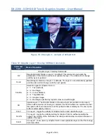
Страница 55: ...2 4 8 1 11 5 3 Frame Counter Example 3 Show the message Frame Count in the top left corner of the video and show the frame counter below it The text properties are set for default white text with no background S1F008 S1X0050 S1T Frame Count S1S SF1Y0045 SF1X0050 SFM4 Figure 20 Frame Counter text display Example 3 ...

Страница 56: ...he text is placed at the bottom of the video SFnnRrrr Set the Red color value of string nn rrr must be a number between 1 and 3 digits in length and in the range 000 and 255 SFnnGggg Set the Green color value of string nn ggg must be a number between 1 and 3 digits in length and in the range 000 and 255 SFnnBbbb Set the Blue color value of string nn bbb must be a number between 1 and 3 digits in l...

Страница 57: ...s avoids a frame without the frame the frame counter display but delays the buffer switch This is the factory default setting SFC1 Enable drop frame timecode for 29 97 and 59 94 frames per second modes Drop frame timecode is enabled by default SFC0 Disable drop frame counting for 29 97 and 59 94 frames per second modes SFT HH MM SS or SFT HH MM SS FF Set the value of the frame counter for Mode 1 f...

Страница 58: ...mmands In the case of the Graphic Overlay Commands it may be more convenient to use these commands because the layer number is included in the command as a parameter to allow the command to be executed without need of changing the active graphics layer The Low Level Buffer Control Commands are LnnnB LnnnW LnnnC and LnnnS When nnn is 1 these commands are equivalent to the SW SW SC and SS commands W...

Страница 59: ...erlay has been reduced in size via the LnnnKxxxx yyyy command it is then possible to change the x y position of the overlay item within the boundaries of the output video This process can then be used for moving panning an OSD target marker around the displayed video The LnnnPxxxx yyyy sets the x and y position of the overlay The overlay must always fit completely within the boundaries of the outp...

Страница 60: ...er number s See LnnnZ Set the size and visibility of Layer n to default The defaults are visible and the same size as the output video of the DX 2200 TI 03 nnn is the layer number s See LnnnKxxxx yyyy Set a preferred size for an overlay layer xxxx and yyyy are numbers between 1 and 4 digits in length The size of an overlay cannot be less than 16 pixels in either direction Setting xxxx 0 and or yyy...

Страница 61: ...ame user interface function The number of switches assigned determines how many different operations can be selected from the user interface function When one switch is assigned two operations are available Two switches allow four operations three switches allow eight operations and four switches allow the selection of 16 operations The factory default settings for the Toggle Switch are listed in ...

Страница 62: ...ds the command S3V to the previous commands Executing UF07 00 clears any command that was previously assigned to Selection 00 of user function 07 When executing the UF commands the command response either or indicates only that the syntax of the UF command was accepted It does not indicate the command string being assigned to the user interface function is correct Commands can be tested by executi...

Страница 63: ...the TL TR commands will continue to function TE Enable the toggle switch UD Disable the DIP switches UE Enable the DIP switches UU Read the DIP switches immediately and execute the commands for the current setting U0 DIP switch settings are applied only when the DIP switches are changed This mode may be useful when the DX 2200 is operating primarily under SERIAL control but the DIP switches are al...

Страница 64: ...the GPS are stored in dedicated data fields in the product By sending commands to the DX 2200 it can be configured to use contents of selected data fields to set the text string for specified Graphic Fields The usual Graphic Field commands for visibility font color position etc determine how the data is displayed on the overlay This allows the DX 2200 to overlay information such as date time and p...

Страница 65: ...r The wiring of the GPS receiver to the DX 2200 will depend on the model of GPS receiver that is used Refer to the GPS receiver documentation for details Table 17 DB9 Serial Y Splitter Cable Pin Connections DB9 Male Pin DX 2200 Signal Direction Function DB9 Female Connection 2 DX 2200 TxD Output Control Port COM1 pin 2 3 DX 2200 RxD Input Control Port COM1 pin 3 5 Signal Ground COM1 COM2 pin 5 7 D...

Страница 66: ...provide the data If the GPS has not been configured to output one or more of the sentences for a data field then that field will contain an empty string Refer to the instruction manual of your GPS to determine how to configure it to provide the required sentences Refer to the NMEA 0183 standards or your GPS instruction manual for more information about the data format of your GPS Table 18 GPS Data...

Страница 67: ...el m GPGGA 12 Geoidal height m GPGGA 13 GPS quality indication GPGGA 14 Satellites in use GPGGA 15 Horizontal dilution of precision GPGGA GPGSA 16 Position dilution of precision GPGSA 17 Time dilution of precision PGRMF 18 Vertical dilution of precision GPGSA 19 Fix Type 1 2 3 GPGSA 20 Status A Valid V NAV GPRMC GPGLL 21 Magnetic variation degrees GPRMC 22 Magnetic variation direction GPRMC 23 Mod...

Страница 68: ... PGRME 42 Estimated position error Meters PGMRE 43 Garmin user defined ID Garmin Proprietary PGRMID 44 Garmin unit ID Garmin Proprietary PGRMID 45 Garmin product model and software version Garmin Proprietary PGRMT 46 True east velocity PGRMV 47 True north velocity PGRMV 48 Up velocity PGRMV 49 True course over ground integer PGRMF 50 Fix Type 0 1 2 PGRMF 51 Satellites in view GPGSV 52 Position dil...

Страница 69: ... ratio dB GPGSV 80 Satellite PRN number GPGSV 81 Satellite elevation 0 to 90 degrees GPGSV 82 Satellite azimuth 0 to 359 degrees GPGSV 83 Satellite signal to noise ratio dB GPGSV 84 Satellite PRN number GPGSV 85 Satellite elevation 0 to 90 degrees GPGSV 86 Satellite azimuth 0 to 359 degrees GPGSV 87 Satellite signal to noise ratio dB GPGSV 88 Satellite PRN number GPGSV 89 Satellite elevation 0 to ...

Страница 70: ...hat text will be stored in mm is the GPS data field number to read and ff is the formatting mode The following CC command example sets the text content for Graphic Field 01 and specifies that it should be set using GPS data field 3 Latitude Format method 1 is used in this example which is a simple copy of the GPS data directly to the Graphic Field CC01F3M1 The available formatting options are desc...

Страница 71: ...yntax is CCmmFnnM4 Bd where d specified 12 hour clock format as described in format mode 3 above Optional parameter A cannot be used in this format mode For example CC01F01M4 formats the time as HH MM and the command CC01F01M4B0 formats the time as HH MM with the time converted to 12 hour format and no am pm indication 5 Copy a substring from the GPS data field to the Graphic Field The syntax is C...

Страница 72: ...t the baud rate to 19200 Table 20 GPS Interface Setup Command Command Description CSE Enable the following functions capturing of GPS data copying of data from GPS fields to Graphic Fields graphic overlay updates on new data or timer CSD Disable the following functions capturing of GPS data copying of data from GPS fields to Graphic Fields graphic overlay updates on new data or timer CSDE Enable c...

Страница 73: ...copying from GPS fields to Graphic Fields a maximum of 31 characters are allowed CTA msg Transmit a message to the GPS appending the asterisk checksum and carriage return linefeed For example CTA PGRMO PGRMC 1 CTB msg Transmit a message to the GPS Only the characters in msg are transmitted The checksum carriage return and line feed must be included in the string For example CTB PGRMO GPGSV 0 22 r ...

Страница 74: ...aster update rate and time resolution of 0 1 second were used instead the output would count as expected CSMn Frame Counter synchronization mode After the frame counter time clock has been set it runs from a crystal oscillator on the DX 2200 and will gradually drift from real time Synchronization modes provide a method to keep the time clock synchronized with the GPS n 0 no synchronization The fra...

Страница 75: ... 3 position S3F28 graphic field 3 font S3S graphic field 3 show CC03F03M6A04 store GPS latitude Use Graphic Field 04 to display GPS Longitude S4X300 graphic field 4 position S4Y60 graphic field 4 position S4F28 graphic field 4 font S4S graphic field 4 show CC04F05M6A06C0 store GPS longitude Use Graphic Field 05 to display true course over ground S5X650 graphic field 5 position S5Y20 graphic field ...

Страница 76: ...er Time Clock set by the GPS In this example the GPS interface is enabled and used to set the time clock in the Frame Counter The frame counter is displayed in the top left corner of the screen Mode 7 is selected to show the time clock display mode with 2 decimal places Refer to the Frame Counter commands for more information CSE enable GPS interface CSM1 adjust Frame Counter timeclock to stay in ...

Страница 77: ...ved it If the DX 2200 firmware is updated the saved configuration will be lost 3 Baud rate cannot be saved in the configuration The DX 2200 always starts at 115200 baud Table 21 Flash Serial Command Codes Command Code Mode of Operation Flash Write Erase Reset Commands FW Write the current configuration to the flash memory The saved configuration will be loaded whenever the DX 2200 starts FE Erase ...

Страница 78: ...n this command reports a video resolution it only indicates that the input video is recognized by the DX 2200 It does not mean the input is compatible with the current operating mode of the product or that it is available for display See also the RIn commands RIn Report input video resolution at input n where n 1 for input 1 and n 2 for input 2 When these commands are received the DX 2200 outputs ...

Страница 79: ...er 1 On Off This switch executes the L1T command to toggle the visibility of the text layer Toggle Right TR Toggle the Graphics Layers 2 and 3 On Off This switch executes the L2T and L3T commands to toggle the visibility of both layers 4 8 2 2 Bypass Saved Configuration Using Toggle Switch The DX 2200 normally loads the saved configuration at power up If the saved configuration is corrupted then i...

Страница 80: ...PiP mode position to the upper right corner Set Scaler mode zoom 100 equivalent Serial Commands P1 ZS100 OFF ON x x Set PiP mode position to lower right corner Set Scaler mode zoom to 125 equivalent Serial Commands P2 ZS125 ON OFF x x Set PiP mode position to upper left corner Set Scaler mode zoom to 150 equivalent Serial Commands P3 ZS150 ON ON x x Set PiP mode position to lower left corner Set S...

Страница 81: ...t 240 by 135 pixels each When an image is uploaded an identification number ID is assigned to the image The ID is used to select that image when it is to be displayed on the overlay It is recommended to keep a record of the ID number used when images are uploaded The DX2200 Software Uploader program can show a list of images that are stored in the memory with their sizes and ID and also reports ho...

Страница 82: ...background buffer is not cleared after the swap and only changing Text Fields are rendered in the background buffer The results of the two methods are provided in the following sections 6 1 Standard Text String Update Benchmark Measurements In this test a number of characters were written through the Serial Port of the DX 2200 TI for OSD using three font sizes the F001 small 26 pixel height F002 m...

Страница 83: ... text field in the back buffer and then switches buffers without clearing the non changing text This results in a lower frame delay in the display of text The results are summarized below Table 26 Update Rate for Low Level String Commands Font Video of Characters Frames to Update Output Written Changing F001 720p60 20 20 2 F001 1080p30 20 20 1 F002 720p60 20 20 3 F002 1080p30 20 20 2 F003 720p60 2...

Страница 84: ...ue Symbol Char Hex Value Symbol Char Hex Value space 0020 7 0037 L 004C 0021 8 0038 M 004D 0022 9 0039 N 004E 0023 003A O 004F 0024 003B P 0050 0025 003C Q 0051 0026 003D R 0052 0027 003E S 0053 0028 003F T 0054 0029 0040 U 0055 002A A 0041 V 0056 002B B 0042 W 0057 002C C 0043 X 0058 002D D 0044 Y 0059 002E E 0045 Z 005A 002F F 0046 005B 0 0030 G 0047 005C 1 0031 H 0048 005D 2 0032 J 004A 005E 3 ...

Страница 85: ...00BC Ô 00D4 ì 00EC 00A5 00BD Õ 00D5 í 00ED 00A6 00BE Ö 00D6 î 00EE 00A7 00BF 00D7 ï 00EF 00A8 À 00C0 Ø 00D8 ð 00F0 00A9 Á 00C1 Ù 00D9 ñ 00F1 ª 00AA Â 00C2 Ú 00DA ò 00F2 00AB Ã 00C3 Û 00DB ó 00F3 00AC Ä 00C4 Ü 00DC ô 00F4 00AD Å 00C5 Ý 00DD õ 00F5 00AE Æ 00C6 Þ 00DE ö 00F6 00AF Ç 00C7 ß 00DF 00F7 00B0 È 00C8 à 00E0 ø 00F8 00B1 É 00C9 á 00E1 ù 00F9 00B2 Ê 00CA â 00E2 ú 00FA 00B3 Ë 00CB ã 00E3 û 00FB...

Страница 86: ...and exclusive remedy and the entire liability of Microtronix under this limited warranty will be at Microtronix s option firmware replacement or firmware upgrade repair In no event does Microtronix warrant that the Software is error free or that the Customer will be able to operate the Software without problems or interruptions 8 2 1 Limited Liability Microtronix Products are not designed or appro...

Страница 87: ...DX 2200 SD HD SDI Text Graphics Inserter User Manual Page 87 of 103 ...

Страница 88: ...ardware used in each of the two product configurations A 1 SDI Video Interfaces The DX 2200 TI supports one SD HD SDI input and one SD HD SDI output port These interfaces support SMTP 292M video formats The SDI output is reclocked from a Gennum Timing Generator which runs asynchronously to the video inputs A 2 RS 232 Serial Control Port The RS 232 Serial Control Port is used to control the text ov...

Страница 89: ...al Control Port is also available on J2 a 3 pin 1mm header JST part number BM03B SRSS TB LF SN available from Digi Key 455 1789 1 ND The pins assignments are listed in the following table Table 30 RS 232 3 Pin Header J2 Pin Signal Direction Signal Name 1 Input Receive Data 2 Signal Ground 3 Output Transmit Data A 3 Power Requirements The board is powered from a standard 5 5mm center positive 5 12V...

Страница 90: ...st be version 12 1 or later to load the JIC programming files for the DX 2200 TI 2 From the Tools menu select Programmer 3 Click Auto Detect 4 A dialog box may appear with a selection for EP3C120 or EP4CE115 Select EP3C120 click Close 5 Select the line in the programmer window containing the EP3C120 device 6 Click Change File and browse to the jic file to load Select it and click Open 7 Check the ...

Страница 91: ...DX 2200 SD HD SDI Text Graphics Inserter User Manual Page 91 of 103 Figure 27 DX 2200 Board PN P4115 TI 24 Mechanical Drawing ...

Страница 92: ...DX 2200 SD HD SDI Text Graphics Inserter User Manual Page 92 of 103 ...

Страница 93: ... serial port i e most PCs today The software drivers for the ICUBS232V2 adapter are supplied by StarTech and are available for free download from www startech com downloads Connect to the website using a browser and search for the product using product ID ICUSB232V2 and click Search Select the product from the search results and download the available Prolific_PL23203 zip file Once downloaded righ...

Страница 94: ...al line enter the assigned Port i e COM3 ii Set Speed to 115200 iii For Connection type select Serial iv Under Saved Session Assign a name to this user setting i e DX 2200 Serial v Save the configuration b Select the Terminal item i Additionally check the boxes for 1 Implicit CR in every LF and for 2 Implicit LF in every CR c Select the Serial item i Set the Serial line to the required come port i...

Страница 95: ...DX 2200 SD HD SDI Text Graphics Inserter User Manual Page 95 of 103 Figure 29 PuTTY Session User Settings Figure 30 PuTTY Terminal Settings ...

Страница 96: ...DX 2200 SD HD SDI Text Graphics Inserter User Manual Page 96 of 103 Figure 31 PuTTY Serial Port Settings ...

Страница 97: ...DX 2200 SD HD SDI Text Graphics Inserter User Manual Page 97 of 103 ...

Страница 98: ...diators Operation is subject to the following two conditions 1 This device may not cause harmful interference and 2 this device must accept any interference received including interference that may cause undesired operation This equipment has been tested and found to comply with the limits for a class A digital device pursuant to Part 15 of the FCC Rules These limits are designed to provide reason...

Страница 99: ...acteristics Limits and Methods of Measurements and CISPR 22 2008 09 EN 55022 2010 Class A Information Technology Equipment The results and observations recorded were in compliance to the requirements TEST LABORATORIES UltraTech Engineering Labs Inc 3000 Bristol Circle Oakville ON Canada L6H 6G4 DATE OF ISSUE OF DECLARATION May 8 2013 Manufacturer Company Name Microtronix Datacom Ltd Signature Norm...

Страница 100: ......

Страница 101: ......

Страница 102: ......

Страница 103: ......

Отзывы: