background image

                                                                     Operator Maintenance    95

_______________________________________________________________________________________________

_______________________________________________________________________________________________

MICROPLEX

Operator‘s Manual SOLID T4 / T5 / T6 / T8

Edition 2.0


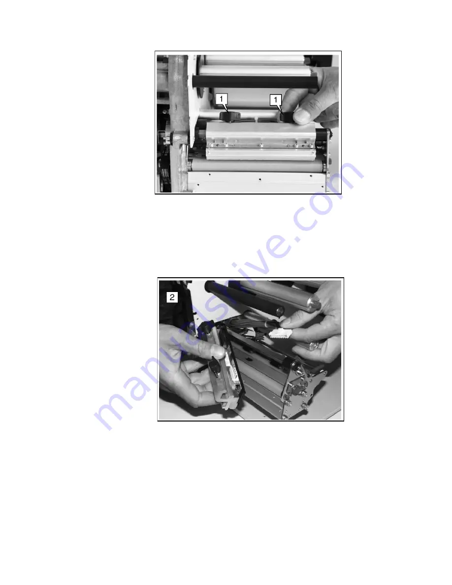
Fig. 7.2.1.a  Unscrewing the two thumb screws

6. The printhead is provided with two lead wires. Pull out both
    plugs in a horizontal direction from the printhead.

7. Remove the old printhead from the device.


Fig. 7.2.1.b  Removing the printhead

8. Take the 

new printhead

 and note the 

resistance-

    value

 printed on the new printhead due to the later setting

    (inscription: R = ..., value in Ohm).

9. Connect the new printhead to the printer using the two plug
    connections.

Содержание LOGIJET T4

Страница 1: ...__________________________________________________________________ ________________________________________________________________________________ SOLID T8 SOLID T6 SOLID T5 SOLID T4 Operator s Manua...

Страница 2: ...2 _______________________________________________________________________________________________ _______________________________________________________________________________________________...

Страница 3: ...ty 10 1 4 General Safety Regulations 10 2 Installation 13 2 1 Check List 13 2 2 Printer Unpacking 14 2 3 Printer Installation 16 2 4 Printer Components 17 3 Basic Operation Sequences 18 3 1 Overview 1...

Страница 4: ...s 47 6 1 Print Process Selecting 47 6 2 Media Setting Material Label or Continuous 49 6 3 Page Length Adjustment 50 6 4 Material Width Adjustment Paper Width 51 6 5 Configuration of Text Margins 52 6...

Страница 5: ...ting the Sync Sensor Level 79 6 28 Setting the Sync Sensor Sensitivity 80 6 29 Selecting the Light Sensor Type 81 6 30 Selecting the Cut Mode 82 6 31 Adjusting the Cutting Position 86 6 32 Configurati...

Страница 6: ...____________________________________________________________________________ _______________________________________________________________________________________________ MICROPLEX Operator s Manual...

Страница 7: ...LID T4 SOLID T5 SOLID T6 and SOLID T8 are all provided with a controller that is also used in SOLID laserprinters So the advantages of the thermal print technology are combined with the flexibility of...

Страница 8: ...pecial ribbon thermal transfer printing or a special kind of paper thermal direct printing While thermal transfer printing the dots touch the thermal ribbon so that the heating of particular dots lead...

Страница 9: ...ible source of danger If you do not pay attention to this information injuries may result the function of the printer could be reduced or objects could be damaged This symbol refers to important hints...

Страница 10: ...vices The determinations of the product standard concerning high frequency interferences of information technology devices EN 55022 class A DIN VDE 0878 electromagnetic interference are complied Also...

Страница 11: ...e is appropriately grounded Install the device on solid and level ground Only trained staff are authorized to transport the equipment Only use consumables which are specially developed for this device...

Страница 12: ...cutter may only be installed by trained personnel Only attach or remove the printhead when the device is switched off After switching off the device wait at least 3 minutes before removing the printh...

Страница 13: ...stallation 2 1 Check List First of all place the printer and the accessories onto a level surface until the definitive location is chosen Please make sure that all items are included and that there ar...

Страница 14: ...5 T6 T8 Edition 2 0 2 2 Printer Unpacking 1 Open the box and remove the parts lying on top 2 Remove the foam covering 3 Take hold of the SOLID printer from the bottom and lift it out the box carefully...

Страница 15: ...__________________________________________ MICROPLEX Operator s Manual SOLID T4 T5 T6 T8 Edition 2 0 5 Turn the device to the position in which it is to be used Fig 2 2 c Printer turned to the right p...

Страница 16: ...to be easily accessible The printer should not be located near volatile or combustible materials e g a curtain The printer must be connected to an appropriate AC power source 120V AC 60 Hz North Ameri...

Страница 17: ..._______________________________________________________ MICROPLEX Operator s Manual SOLID T4 T5 T6 T8 Edition 2 0 2 4 Printer Components Main view hood panel display Fig 2 4 a Main view of the printer...

Страница 18: ...in t p r o c e s s s e le c tin g th e r m a l d ir e c t th e r m a l tr a n s f e r r ib b o n r e m o v a l r ib b o n lo a d in g m e d i a lo a d in g m e d i a s e tt in g la b e l c o n tin u...

Страница 19: ...e panel settings above shall be effective permanently that means they do not have to be put in again after a printer OFF ON the setting values can be saved permanently by operating the ON LINE key thr...

Страница 20: ...diagram when inserting changing material and ribbon Also pay attention to the instructions located on the inside of the device hood Ribbon and material should only be inserted changed by specially in...

Страница 21: ...Off Media Loading To load roll fed media for tear off respectively for further external processing go on like this F The tear off roll fed media is easier to insert if the end is gored before inserti...

Страница 22: ...ll should turn in an anti clockwise direction when unwinding Take the Tear off roll fed media and hold it in the corresponding way 5 Push the material onto the unwinder with the appropriate adapter ri...

Страница 23: ...4 of the infeed to raise the contact rollers Keeping the load lever 4 pressed down push the beginning of the material through the material guide until it is underneath the printhead load lever Fig 4...

Страница 24: ..._____________________ MICROPLEX Operator s Manual SOLID T4 T5 T6 T8 Edition 2 0 Safety instructions The cutter optional can cause injuries if the printer is operated incorrectly There is a danger of f...

Страница 25: ...printer 3 Press the lift lever to remove the material see chapter 4 1 Item 20 in the Winding Diagram and at the same time pull away the material to the rear The material can also be expelled from the...

Страница 26: ...sed compare chapter 1 1 F Make sure you always use a printer ribbon being wider than the media to print on In the case of printing on abrasive media printhead damaging can be avoided this way To set t...

Страница 27: ...e printhead bracket and the material contact roller 3 7 Then pull up the ribbon and drape it over the guide mandrel compare Fig 4 3 1 b 8 Feed the ribbon under the take up mandrel 4 and secure it to t...

Страница 28: ...____________________________________________ _______________________________________________________________________________________________ MICROPLEX Operator s Manual SOLID T4 T5 T6 T8 Edition 2 0 t...

Страница 29: ...nding roll up torque has to be increased when the ribbon is slack or has folds or the ribbon is not wound up tightly enough on the roll up mandrel The unwinding roll up torque has to be decreased when...

Страница 30: ...________________________________________________________________________ MICROPLEX Operator s Manual SOLID T4 T5 T6 T8 Edition 2 0 ribbon unwind mandrel plastic hexagonal nut Fig 4 3 2 b Setting the b...

Страница 31: ...he hood of the printer 3 The core of a used up ribbon can be removed by pulling it from the ribbon mandrel compare figure 4 3 1 a 4 If the inserted ribbon is not used up cut it close to the ribbon tak...

Страница 32: ...e Photoelectric Switch The printers SOLID T4 SOLID T5 SOLID T6 and SOLID T8 are provided with transparency photoelectric switches The photoelectric switch 2 can be adjusted using the red adjustment kn...

Страница 33: ...anual SOLID T4 T5 T6 T8 Edition 2 0 scale adjustment knob Fig 4 4 b Adjustment knob for the photoelectric switch photoelectric switch Fig 4 4 c Photoelectric switch For the adjustment of the photoelec...

Страница 34: ...______________________________________ _______________________________________________________________________________________________ MICROPLEX Operator s Manual SOLID T4 T5 T6 T8 Edition 2 0 Example...

Страница 35: ...width and or material thickness have an effect on the contact pressure of the thermal bar on the feed roller To compensate this influence the contact pressure can be set in 3 stages Setting 1 for thin...

Страница 36: ...ng 1 setting for thin narrow material For medium head contact pressure turn the arrow to Setting 2 until it lightly clicks into place To get a further increased printhead s contact pressure turn the a...

Страница 37: ...2mm from the left edge of the label to 13mm does not apply for SOLID T4 1 For adjustment first loosen the two thumb screws 1 thumb screws Fig 4 6 a Loosening the thumb screws The printhead may and mus...

Страница 38: ...______________________________________________________________________________________ MICROPLEX Operator s Manual SOLID T4 T5 T6 T8 Edition 2 0 plastic discs Fig 4 6 b Loosening the screws of the pla...

Страница 39: ...ch the printer to the network The printers SOLID T4 SOLID T5 SOLID T6 and SOLID T8 are provided with several interfaces see figure 2 4 b and chapter 9 Specifications for more information 5 2 Turning o...

Страница 40: ...______________________________________________________ MICROPLEX Operator s Manual SOLID T4 T5 T6 T8 Edition 2 0 5 3 Control Panel View ON LINE SOLID T8 display two lined function 4 units keys ON LINE...

Страница 41: ...ROG ESC ON LINE Now the individual control panel keys are described The ON LINE key is used to turn the printer OFF LINE or ON LINE In addition to that this key can be used to clear an error message i...

Страница 42: ...egrated website with information on the printer status and the printjob status Chapter 6 Panel Functions describes how to reach the particular printer functions via the panel T e m p o r a r y changes...

Страница 43: ...RS 232 Protocol RTS CTS XON XOFF Baudrate RS 232 Format MP BUS Emulation Language Input Buffer Transparent Code Config Word User Config Select Define Factory Default Page Menu Font Number Orientation...

Страница 44: ...E PROG ESC CUT FEED Menu Level ON LINE Function This symbol shows the ON LINE key The printer is turned OFF LINE with this key With this key you get into the first menu level of the menu structure By...

Страница 45: ...the selected function is activated the changes are stored temporary To select such changes permanently the user must terminate the change of function by pressing the ON LINE key three times These perm...

Страница 46: ...agrams show the course necessary in order to activate a certain function First the elements of the diagram are explained The sequence on the left describes which keys have to be pressed briefly in suc...

Страница 47: ...printer is presumed to be turned on and in the ON LINE mode 6 1 Print Process Selecting This function allows to select the print process While thermal direct printing the device operates without ribbo...

Страница 48: ...ess Thermo direct Thermo transfer Thermo transfer Notes Turn the printer OFF LINE with this key The PROG ESC key gives the user access to the menu structure Press the FEED s or CUT t key until Engine...

Страница 49: ...INE PROG ESC FEED ON LINE FEED ON LINE FEED ON LINE ON LINE Panel display ON LINE OFF LINE Menu Level 1 Paper Menu Page Length Material Label Continuous Continuous Notes Turn the printer OFF LINE with...

Страница 50: ...l 1 Paper Menu Page Length in mm Digit1 280 1 Digit1 282 5 Digit1 282 5 Notes Turn the printer OFF LINE with this key The PROG ESC key gives the user access to the menu structure Press the FEED s or C...

Страница 51: ...m Digit1 210 3 Digit1 210 0 Digit1 210 0 Notes Turn the printer OFF LINE with this key The PROG ESC key gives the user access to the menu structure Press the FEED s or CUT t key until Paper Menu is di...

Страница 52: ...el display ON LINE OFF LINE Menu Level 1 Page Menu Font Number Margin Left Right Digit1 02381 Digit1 02387 Digit1 02387 Notes Turn the printer OFF LINE with this key The PROG ESC key gives the user ac...

Страница 53: ...erates a status sheet The status sheet contains information about the current printer configuration and the available fonts ON LINE PROG ESC ON LINE ON LINE ON LINE Panel display ON LINE OFF LINE Menu...

Страница 54: ...entitled SERVICE INFORMATION contain hexadecimal coded configuration parameters Printed in plain text Controller version memory serial number Firmware release Interface parameters of Parallel Serial U...

Страница 55: ...rinter The font list shows demo prints of all fonts and in addition the concerning PCL selection commands These commands contain information on font width and font hight see chapter 6 19 Font Selectio...

Страница 56: ...de can be activated only temporarily ON LINE PROG ESC ON LINE FEED ON LINE ON LINE Panel display ON LINE OFF LINE Menu Level 1 Status Sheet Hexdump Hexdump Notes Turn the printer OFF LINE with this ke...

Страница 57: ...FORM FEED ON LINE PROG ESC ON LINE FEED ON LINE ON LINE Panel display ON LINE OFF LINE Menu Level 1 Status Sheet Normal Print FF Normal Print FF Notes Turn the printer OFF LINE with this key The PROG...

Страница 58: ...cular page after a print interruption e g paper jam The data contained in the input buffer before the interruption are cleared ON LINE PROG ESC ON LINE FEED ON LINE ON LINE Panel display ON LINE OFF L...

Страница 59: ...l functions Note When printing the menu page please use a large paper ON LINE PROG ESC ON LINE FEED ON LINE ON LINE Panel display ON LINE OFF LINE Menu Level 1 Status Sheet Menu Page Menu Page Notes T...

Страница 60: ...a to the printer These test prints facilitate error analysis ON LINE PROG ESC ON LINE FEED ON LINE ON LINE Panel display ON LINE OFF LINE Menu Level 1 Status Sheet Sliding Pattern Sliding Pattern Note...

Страница 61: ...e for print data transfer ON LINE PROG ESC FEED ON LINE ON LINE FEED ON LINE ON LINE Panel display ON LINE OFF LINE Menu Level 1 Configuration Interface SIA Centronics Centronics Notes Turn the printe...

Страница 62: ...LINE FEED ON LINE FEED ON LINE ON LINE Panel display ON LINE OFF LINE Menu Level 1 Configuration Interface Emulation SOLID Standard HP PCL 5 HP PCL 5 Notes Turn the printer OFF LINE with this key The...

Страница 63: ...OPLEX Operator s Manual SOLID T4 T5 T6 T8 Edition 2 0 Available Emulations Standard MICROPLEX IDOL HP LaserJet PCL 5 Epson FX IBM Proprinter Diablo 630 Optional Kyocera Prescribe Express Printronix IG...

Страница 64: ...the font list ON LINE PROG ESC FEED ON LINE FEED ON LINE FEED ON LINE ON LINE Panel display ON LINE OFF LINE Menu Level 1 Configuration Interface Language German English English Notes Turn the printe...

Страница 65: ...PROG ESC FEED ON LINE FEED ON LINE FEED ON LINE ON LINE Panel display ON LINE OFF LINE Menu Level 1 Configuration Interface Transparent Code Digit1 2625 Digit1 2626 Digit1 2626 Notes Turn the printer...

Страница 66: ...G ESC FEED ON LINE FEED ON LINE FEED ON LINE ON LINE Panel display ON LINE OFF LINE Menu Level 1 Configuration Interface Input Buffer 32 kB 100 kB 100 kB Notes Turn the printer OFF LINE with this key...

Страница 67: ...tions to factory defaults ON LINE PROG ESC FEED ON LINE FEED ON LINE ON LINE Panel display ON LINE OFF LINE Menu Level 1 Configuration Interface Factory Default Factory Default Notes Turn the printer...

Страница 68: ...he list of available fonts ON LINE PROG ESC FEED ON LINE ON LINE FEED ON LINE ON LINE Panel display ON LINE OFF LINE Menu Level 1 Page Menu Font Number Font 600 Font 5507 Font 5507 Notes Turn the prin...

Страница 69: ...2 10 12 Kurilen Italic 0610 12 10 1 Kurilen 1710 12 10 1 Kurilen Italic 4508 P 8 1 Helgoland 4510 P 10 Helgoland 4714 P 14 4 Helgoland Bold 5507 20 7 Langeoog 5508 16 6 7 9 Langeoog 5509 15 9 1 Langeo...

Страница 70: ...d 2200 P SC Texel Italic 2300 P SC Texel Bold Italic 9800 P SC Neuwerk Italic 9500 P SC Neuwerk Bold Italic 9600 P SC Neuwerk Bold 0060 SC Plakatschrift 9501 P SC Neuwerk II Condensed Italic 9601 P SC...

Страница 71: ...Menu Font Number Orientation Orientation 0 Orientation 1 Orientation 1 Notes Turn the printer OFF LINE with this key The PROG ESC key gives the user access to the menu structure Press the FEED s or CU...

Страница 72: ...E FEED ON LINE FEED ON LINE ON LINE Panel display ON LINE OFF LINE Menu Level 1 Page Menu Font Number Symbol Code 902 IBM PC II 901 IBM PC I 901 IBM PC I Notes Turn the printer OFF LINE with this key...

Страница 73: ...FEED ON LINE ON LINE FEED ON LINE ON LINE Panel display ON LINE OFF LINE Menu Level 1 Engine Paper Move Backward Paper Change Paper Change Notes Turn the printer OFF LINE with this key The PROG ESC ke...

Страница 74: ...the print speed is 4 inch s to 12 inch s ON LINE PROG ESC FEED ON LINE FEED ON LINE FEED ON LINE ON LINE Panel display ON LINE OFF LINE Menu level 1 Engine Paper Move Printspeed 8 inch s 4 inch s 4 i...

Страница 75: ...FEED ON LINE FEED ON LINE ON LINE Panel display ON LINE OFF LINE Menu Level 1 Engine Paper Move Contrast Contrast 85 Contrast 60 Contrast 60 Notes Turn the printer OFF LINE with this key The PROG ESC...

Страница 76: ...can be set in millimeter units By this the position of the printout and cut is adjusted relatively to the gap perforation of the material Setting range 15 to 240 mm feed direction print material Gap...

Страница 77: ...LEX Operator s Manual SOLID T4 T5 T6 T8 Edition 2 0 ON LINE FEED ON LINE ON LINE Panel display Sync Sens Offset Offset 0 0 mm Offset 5 0 mm Offset 5 0 mm Notes The currently set value is displayed Pre...

Страница 78: ...Sync Sens Level and Sync S Sensitiv see the following chapters the contrast value measured by the gap detection can be defined specifically for the label material ON LINE PROG ESC FEED ON LINE FEED O...

Страница 79: ...of the photoelectric sensor is shown on the display of the operating panel For all various contrast zones of the used material contrast results shall be measured now place the material within the phot...

Страница 80: ...ch to the gaps perforations of the actual used material Setting range for the sensitivity of the Sync sensor 10 to 100 The maximum sensitivity of 100 has to be used for narrow gaps perforations The mi...

Страница 81: ...adhesive labels must be defined according to the application The procedure of settings for this panel function Light Sens Type is similar to the panel function Setting the Sync Sensor Mode compare cha...

Страница 82: ...PROG ESC FEED ON LINE FEED ON LINE FEED ON LINE FEED ON LINE ON LINE Panel display ON LINE OFF LINE Menu Level 1 Engine Paper Move Cutting Menu Cutting Pos Cut Mode Real 1 1 Mode Batch Mode Batch Mod...

Страница 83: ...___ MICROPLEX Operator s Manual SOLID T4 T5 T6 T8 Edition 2 0 Real 1 1 Mode The whole surface of the label is printable The label is pushed forward to the cutter for cutting After the cut the beginnin...

Страница 84: ..._ MICROPLEX Operator s Manual SOLID T4 T5 T6 T8 Edition 2 0 Batch Mode The whole surface of the label is printable Cutting takes place during printing This can result in brief interruptions within the...

Страница 85: ...___________ MICROPLEX Operator s Manual SOLID T4 T5 T6 T8 Edition 2 0 Normal 1 1 Mode In this mode cutting takes place during printing As a result the first 18 mm of the label are not printable These...

Страница 86: ...LINE PROG ESC FEED ON LINE FEED ON LINE ON LINE FEED ON LINE ON LINE Panel display ON LINE OFF LINE Menu Level 1 Engine Paper Move Cutting Menu Cutting Pos Position 0 0 mm Position 0 5 mm Position 0...

Страница 87: ...INE FEED ON LINE ON LINE Panel display ON LINE OFF LINE Menu Level 1 Network Off Manual IP Address 192 168 002 002 192 168 010 123 192 168 010 123 Notes Turn the printer OFF LINE with this key The PRO...

Страница 88: ...tes If your network is using DHCP an address can be automatically assigned select the subitem DHCP from the network menu The parameters Subnet Mask and Gateway are configured in the same way as descri...

Страница 89: ...t allowed to perform these operations 7 1 Printer Cleaning By a regular and conscientious performance of the following operations the printer is guaranteed to always work at an optimum reliability For...

Страница 90: ...or s Manual SOLID T4 T5 T6 T8 Edition 2 0 After the cleaning operations please load the wanted consumables again see chapter 4 Handling of Consumables 7 1 1 Printer Cabinet Cleaning Soilings like dust...

Страница 91: ...emble or remove the printhead The printhead can be damaged by electrostatic charges Therefore first of all touch a properly grounded part of the printer f e the base plate of the printer If the printh...

Страница 92: ...you have to unscrew the two thumb screws first until the entire printhead mounting can be removed from the contact shaft Please pay attention to the hints of chapter 7 1 2 Normally the sensor cleaning...

Страница 93: ...e chosen See chapter 4 5 too Only use consumables being specially developed for this device Using unsuitable consumables or excessive contact pressure can result in premature wearing of the printhead...

Страница 94: ...ter 4 3 3 4 Remove the printmedia see chapter 4 2 2 Please pay attention to the following Wait at least 3 minutes after switching off the device before disassembling the printhead The printhead can be...

Страница 95: ...T8 Edition 2 0 Fig 7 2 1 a Unscrewing the two thumb screws 6 The printhead is provided with two lead wires Pull out both plugs in a horizontal direction from the printhead 7 Remove the old printhead f...

Страница 96: ...____________ MICROPLEX Operator s Manual SOLID T4 T5 T6 T8 Edition 2 0 10 Place the new printhead onto the contact shaft in the same way the old one was positioned there see figure 7 2 1 a 11 Move the...

Страница 97: ...ing the printer off If the new printhead meets the requirements an automatically printhead identification happens By activating the Head Resistance Value Setting control panel function the automatical...

Страница 98: ...ON LINE PROG ESC FEED ON LINE FEED ON LINE Panel display ON LINE OFF LINE Menu Level 1 Engine Paper Feed Service Mode Head Resistance Notes With this key the printer has to be turned OFF LINE The PRO...

Страница 99: ...Notes Input of head resistance xxxx old value of head resistance With the FEED s key the value of the actual digit can be changed Digit 1 last digit in the following example 3 With the CUT t key you c...

Страница 100: ...can be modified in order to adapt the characteristics of the consumables An increase of the pressure value for example can improve the transfer of the image onto the printmedia printhead thermal tran...

Страница 101: ...MICROPLEX Operator s Manual SOLID T4 T5 T6 T8 Edition 2 0 F If the print quality with a new printhead isn t even over the whole print width an additional mechanical printhead adjustment is necessary...

Страница 102: ...display Remedies Cover Open close the printer hood Load Paper insert a media roll fed media e g make sure the media has been loaded correctly compare chapter 4 2 clean the sensors see chapter 7 1 3 F...

Страница 103: ...ess selecting and correct it if necessary see chapter 6 1 check the ribbon transport load the ribbon again if necessary see chapter 4 3 increase the contrast see chapter 6 24 choose different consumab...

Страница 104: ...SOLID T4 T5 T6 T8 Edition 2 0 Defect Remedies Printout blurred or incomplete clean the printhead see chapter 7 1 2 check the ribbon transport load the ribbon again if necessary see chapter 4 3 the pr...

Страница 105: ...as been loaded correctly compare chapter 4 3 clean the sensors see chapter 7 1 3 clean the transport rollers see chapter 7 1 4 No straight transport of the consumables torsion or folding of the ribbon...

Страница 106: ...n automatic jam safety function to prevent a loss of data When an error occurs all the pages on the paper path will be printed again This ensures that no data will get lost The exact number of pages t...

Страница 107: ...he working steps necessary for repacking Pay attention to the notices located on the products and the hints given in the Service Manual as well If you are not familiar with any of the working steps pl...

Страница 108: ......

Страница 109: ...dpi dots per inch horizontal and vertical SOLID T4 SOLID T5 SOLID T6 SOLID T8 25 4 to 113 25 4 to 154 30 2 to 185 100 to 254 mm 106 128 160 213 mm 0 2 to 0 9 mm parallel IEEE 1284 Centronics MP BUS Se...

Страница 110: ...eps can be done by the user in accordance with the manual without the usage of tools Consumables can be different depending on the printer type The most important consumable for example is toner Usual...

Страница 111: ...t time to exchange a component depends not only on the failure of a component but also on a possible loss of print quality in the printouts MNPSQ Mean Number of Prints with Specified Quality SQ This v...

Страница 112: ...________________________________________________________________________________ _______________________________________________________________________________________________ MICROPLEX Operator s Ma...

Страница 113: ...iguration via the control panel 42 connect printer to a PC 39 consumables 20 108 contents 3 continuous 49 contrast 75 control panel 39 control panel elements 40 control panel keys 41 conventions 9 cos...

Страница 114: ...16 107 I IDOL 13 65 input buffer 58 66 installation 13 interfaces 61 107 IP address 87 K keys 40 L label 49 language 64 LCD display 40 light sensor type 81 M margin 52 material 7 49 material feed off...

Страница 115: ...urce 16 pressure value 100 print density 109 print process 47 print quality 103 109 print repeat 106 print speed 7 74 107 print width 51 printer components 17 printer installation 16 printhead cleanin...

Страница 116: ...______________________ MICROPLEX Operator s Manual SOLID T4 T5 T6 T8 Edition 2 0 T tear off media 21 temperature 16 107 temporary configuration changes 42 test prints 60 text margins 52 text orientati...

Страница 117: ...___________________________________________________________________________ _______________________________________________________________________________________________ MICROPLEX Operator s Manual...

Отзывы: