background image

Page 105

Visual Camera (only TIM 200/230)

thermoIMAGER TIM Connect

8.3.2 

Transparency of Thermal Image

The thermal image can smoothly be faded into the visual image (0 … 100 %). To set the transparency value please use the Tools, 
Configuration, Measuring colors menu and Standard palette / Transparency [%].

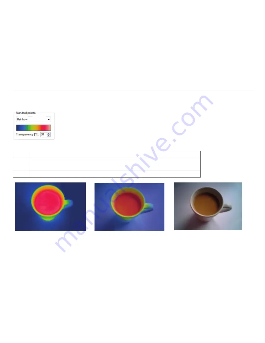
Fig. 99 View Standard palette

0 %

The thermal image is fully faded into the visual image.

50 %

The thermal image is partly (50 %) faded into the visual image.
Using this setting the ideal relation of both images can be defined, see Chap. 

8.3.3

.

100 %

The thermal image is fully transparent and will not be shown in the visual image.

Fig. 100 Cross-fading of thermal image and 
visual image by 0 % setting

Fig. 101 Cross-fading of thermal image and 
visual image by 50 % setting

Fig. 102 Cross-fading of thermal image and 
visual image by 100 % setting

Содержание thermoIMAGER TIM

Страница 1: ...Operating Instructions thermoIMAGER TIM Connect...

Страница 2: ...ON MESSTECHNIK GmbH Co KG K nigbacher Strasse 15 94496 Ortenburg Germany Tel 49 0 8542 168 0 Fax 49 0 8542 168 90 e mail info micro epsilon de www micro epsilon com Software for thermoIMAGER TIM Infra...

Страница 3: ...1 2 Temperature Unit 20 4 1 3 Temperature Range Scaling of Reference Bar 20 4 1 4 Displayed Frame Rate 22 4 1 5 Change of the Title Bar 23 4 1 6 Lock Unlock Application 23 4 1 7 Optimization of Softwa...

Страница 4: ...on IPC 46 4 5 2 COM Port 47 4 6 Start Options 48 4 6 1 Overview of Start Options 48 4 6 2 Start of Multiple Software Imager Instances 50 5 Data Capturing 52 5 1 Open Files 52 5 2 Replay of Files 52 5...

Страница 5: ...7 6 7 Relative Extreme Values 88 6 8 Alarms 89 6 9 3D Display of Thermal Image 91 6 10 Event Grabber 92 6 11 Zoom Function of Snapshots 94 7 TIM 8 40 95 7 1 Focus Setting 95 7 2 Imager Interfaces for...

Страница 6: ...tion 120 9 3 4 Zoom Function of Snapshots 121 10 Merging 121 10 1 General Information 121 10 2 Direct Connection over USB Port 122 10 3 Configuration 122 10 4 Connection via the Ethernet Network 130 1...

Страница 7: ...edge of the instruction manual 1 1 Symbols Used The following symbols are used in the instruction manual Indicates a situation that may result in property damage if not avoided Indicates a user action...

Страница 8: ...ding on the device max pixels and will be shown as thermographic image using standardized palettes The radiometric processing of the picture data enables the user to do a comfor table detailed analysi...

Страница 9: ...tically Insert the installation CD into the according drive on your computer If the autorun option is activated the installation wizard will start automatically Otherwise please start setup exe from t...

Страница 10: ...taneously e g via USB hub please select the required TIM from the list in the Devices menu 3 3 Choice of Language In the Tools and Language menu you can choose from a variety of available languages i...

Страница 11: ...Page 11 Getting Started thermoIMAGER TIM Connect 3 4 Software Window Example...

Страница 12: ...The value is shown inside the IR image and the control displays 5 Reference bar Shows the scaling of temperature within the color palette 6 Temperature time diagram Shows the temperature curves over t...

Страница 13: ...nnect These additional views are particularly useful when using a touch computer or a tablet The screen and menu are customized and displayed according to their functions Fig 1 Screen View User Mode F...

Страница 14: ...Page 14 Getting Started thermoIMAGER TIM Connect Fig 4 Configuration window for User Touch and Tablet i The User Mode Tablet provides only limited functionality...

Страница 15: ...files recording saving temp time diagram data snapshot screenshot capture screen Edit Editing of sequences and layouts View Display or fade out of different software features Devices Choice of camera...

Страница 16: ...ause Temperature profile vertical Linescanner view Sighting view Stop Temperature time diagram Linescanner configuration Record Digital display group Image subtraction Save snapshot to file Snapshot h...

Страница 17: ...se from a list of color palettes to achieve ideal displaying of the infrared image and the included temperature informa tion Fig 7 Icons for color palette selection Fig 8 Dropdown menu Standard palett...

Страница 18: ...are Configuration thermoIMAGER TIM Connect Available color palettes Iron Gray Black Cold Iron Hi Gray White Cold Rainbow Alarm Red Rainbow Hi Alarm Green Rainbow Medical Alarm Blue Fig 9 Palette selec...

Страница 19: ...ge 19 Software Configuration thermoIMAGER TIM Connect Palette Iron Palette Rainbow Palette Blue Hi Palette Rainbow Hi Palette Rainbow Hi Palette Gray Black Cold Fig 10 Examples of various color palett...

Страница 20: ...ius C and Fahrenheit F see Fig 11 Fig 11 View Temperature unit Fig 12 View Temperature unit Alternatively the temperature unit can also be changed by pressing the right mouse button in the live IR im...

Страница 21: ...pixels in the image will be continuously calculated Based on the mean value one standard deviation 1 sigma sets the limits of reference bar 3 s The mean value of all pixels in the image will be contin...

Страница 22: ...camera Skipping It skips so many pictures that the set display frame rate results Average The pixels are averaged out of a sequence of images This weakens the detector noise Minimum From a sequence of...

Страница 23: ...ck Application The software offers the possibility to block or unlock the application by entering a password This is possible under menu Help and Lock unlock application Enter a password and repeat it...

Страница 24: ...ighest resolution but requires a higher computing power Using a slow computer it is recommended to choose the option Performance Is the bar placed in the middle you get a compromise between quality an...

Страница 25: ...ndow can be positioned separately on the screen On the other hand a window can be set at a fixed position in the software The location can be determined using the positioning field mouse over the arro...

Страница 26: ...idual display of software you can show or hide single bars in the software window There is the possibility to Show all bars or Hide all bars by one click Fig 22 View bars i All icons shown on the tool...

Страница 27: ...ou can decide which information you would like to see inside the infrared image window Via Reference bar you can set the position of the temperature scale within the infrared image window Fig 23 View...

Страница 28: ...Digital display group temperatures allows the user to define which temperature control displays will be shown in the application window Temperatures see Chap 4 2 1 The shown pre defined values can al...

Страница 29: ...e pre designed or your own image layouts If you want to use an alternative layout you must activate it under Load layout You can save your own layouts with user defined names Fig 26 View layout manage...

Страница 30: ...t to current file you can save files with a new layout set ting Using Remove layout from current file it is possible to configure a file in a way that it has no associated layout pattern i To confirm...

Страница 31: ...ware Configuration thermoIMAGER TIM Connect Under Tools Configuration and Extended Layout created layouts can be assigned to specific device types These layouts are then only visible for the selected...

Страница 32: ...a full screen mode Please use the menu View and Full screen or the Icon on the toolbar to change the display size 4 2 8 Arranging of Thermal Image The thermal image within the main window of the softw...

Страница 33: ...e Displayed Image Using the Zoom option a detail of the image can be enlarged in the main window by the position information The option can be activated by tagging the Maximal diagonal to the square f...

Страница 34: ...und anschlie ende Vergr erung eines Rechteck Messfeldes 4 3 Image Configuration 4 3 1 Calibration Files The menu Tools Extended and Reimport calibration files enables to boot the calibration data for...

Страница 35: ...to minimize this disturbing effect the offset correction can be initiated manually or by an external control pin at a suitable point of time In the Devices and Refresh flag menu or via the Icon on th...

Страница 36: ...the flag is externally controlled e g via the process interface input see Chap 4 5 Use the flag to protect the detector from potentially dangerous radiation for example laser radiation Damage of the d...

Страница 37: ...a correct temperature measurement The ambient temperature value is delivered by the camera s internal sensor by default Alternatively the value can be set as a fixed value Fig 35 View Emissivity Trans...

Страница 38: ...value can be set within Fixed value If the temper atures are changing slightly within the defined area due to a thermal drift the whole image will be corrected by a certain factor Alternatively the c...

Страница 39: ...andard the camera can be delivered with different type of lenses If the camera is ordered with several additional lenses the currently used optics must be chosen in this menu Fig 37 View Optics With t...

Страница 40: ...l function is the adjustable extended temperature range under Extended The temperature range 150 C 900 C can be extended from 20 C The accuracy between 20 C 150 C is no longer exact This function is u...

Страница 41: ...tively the device framerate can also be changed via the status bar in the TIM Connect software win dow To do this click on the device framerate with the right mouse button With the camera TIM M 1 M 05...

Страница 42: ...e following options Analog Input AI Emissivity Ambient temperature Reference temperature Uncommitted value Flag Control Triggered Snapshots Triggered Recording Triggered Linescanner Triggered event gr...

Страница 43: ...he connected PIF Standard PIF or Industrial PIF An available in or output will be marked with a green checkmark A not available in or output will be marked with a red x With Set number of ports like c...

Страница 44: ...igital input of the PIF simultaneously Fig 42 View configuration If you activate the function Alarm on an analog output you need to assign also in the Alarms tab the desired measurement area to the de...

Страница 45: ...n power supply PIF Shut down of TIMConnect software Crash of TIMConnect software Fail Safe output 0V at analog output AO Open contact fail safe relay red LED on The failsafe function can be activated...

Страница 46: ...via Dynamic Link Library DLL The Internal buffer size is the size of the queue between TIM Connect and Direct SDK unit frames Fig 43 View Mode IPC i Two software development kits are offered Connect S...

Страница 47: ...Tools Configuration External Communication and Comport menu If selected the data values sent out by the camera can be transmitted via specified Port The Baud rate can be changed from 1200 to 921600 ac...

Страница 48: ...h additional starting parameters using the command line see Fig 45 Please change the linkage in the software settings via the launch icon on the desktop Behind the command line please add a space char...

Страница 49: ...ermoIMAGER TIM Connect Starting the software via the launch icon you will get an overview of possible commands Fig 47 View help dialog i Using the parameter Invisible the software can only be closed v...

Страница 50: ...to setup further software instance please follow the steps below Duplicate the software icon at the desktop Optional Change the name of the new software icon at the desktop e g Imager1 Make a right cl...

Страница 51: ...pective software instance see Chap Fig 49 Fig 49 View Application start Starting the software via the new desktop icon the linked imager will be displayed automatically SN is the se rial number of the...

Страница 52: ...he menu File and Reopen you can easily reopen captured files if the option in is activated see Chap 5 1 5 2 Replay of Files 5 3 Control Panel In order to replay a video sequence you can use different...

Страница 53: ...et All mentioned settings can also be changed via the control panels below the main window Fig 51 View Replay Options i The replay settings only refer to the current file shown in the main window All...

Страница 54: ...in the Edit menu A time bar tool is shown on the bottom of the image Set the position marks on the time bar to select the beginning and end of the video sequence you want to be edited The not selecte...

Страница 55: ...de option see Fig 54 Off The recording frame rate corresponds to the device frame rate of the camera Skipping It skips so many pictures that the set display frame rate results Average The pixels are a...

Страница 56: ...Page 56 Data Capturing thermoIMAGER TIM Connect Fig 55 Example diagram Recording frame rate Fig 56 Recording frame rate referring to 1 pixel...

Страница 57: ...d images will be played automatically in the main window The recording contains radiometric Videos RAVI file which allow users to do a detailed post analysis anytime later Moreover new measure areas a...

Страница 58: ...mporarily recorded video file Fig 59 View Temporary Recording File The Estimated file size is estimated to indicate the amount of megabits needed or consumed It can be checked whether the available ha...

Страница 59: ...activated the images will be saved as standard AVI file only containing color information A later conversion of a RAVI file into an AVI file and vice versa is not possible For recording a video seque...

Страница 60: ...on corresponding to the camera s resolution Magnified Magnification for TIM 160 TIM 2xx to four times the resolution for TIM 4xx to double and for TIM 640 and TIM M 1 the original device resolution re...

Страница 61: ...hots The option Max triggered snapshots sets the number of displayed snapshots in the separate window Snapshot history see Chap 4 2 1 If Ignore last snapshot if available is activated only the latest...

Страница 62: ...on in Excel Text Temp profile data csv Saving of temperature profile data only as Text format to edit information in Excel i The TIFF files are saved as radiometric files and can be analyzed in detail...

Страница 63: ...if saving a sequence or snapshot Fig 64 View File name template for triggered recording and snapshots The Path defines the storage location of all files and can be changed here Once recorded the file...

Страница 64: ...iguration and Trig Recording Snapshots see Chap 5 6 5 If a shot snapshot is to be opened from the snapshot history there are several options Open Opens the snapshot in the same instance see Chap 5 1 O...

Страница 65: ...w can be copied to the clipboard in order to paste it into different programs such as MS Word Alternatively you can also copy the whole software window screenshot to the clipboard us ing the File Scre...

Страница 66: ...lternatively press the Alt F7 key or the adjacent icon The following setting options can be found in the configuration menu under the tab Capture screen Under Capture mode you can choose be tween Appl...

Страница 67: ...will pop up prompting you to enter a loca tion and a save name Generate file name by template Here you can enter a Prefix for filename a Path and a Sample for the recording Static filename Under the n...

Страница 68: ...he Remove button deletes an existing Measure area Calculated area Press Up Down to position individual measure areas within the list One measure area from the list can be appointed as the Main measure...

Страница 69: ...moIMAGER TIM Connect Available measure area shapes are Position X Y User defined rectangle Measure point 1x1 Measure point 2x2 Measure point 3x3 Measure point 5x5 Ellipse Polygon Spline Kurve Fig 67 V...

Страница 70: ...e realized directly at the measuring field in the main window By moving the cursor to the edges of the measuring field the grippers can be used to adjust the size of thermal image or to move the image...

Страница 71: ...age 71 Data Processing thermoIMAGER TIM Connect Fig 68 View Position Fig 69 Measure area assigned to a tempera ture profile measure point Fig 70 Measure area assigned to a temperature profile rectangl...

Страница 72: ...that offer a signal processing The name for the created object can be changed in the field Name Furthermore in the field Show in digital display group you can decide whether the object is to be displ...

Страница 73: ...w time constant and will follow the current object temperature There fore if periodic events will be measured bottles on a conveyor e g this peak hold function avoids a drop down of the signal to the...

Страница 74: ...Data Processing thermoIMAGER TIM Connect Area 1 without post processing Object 1 with averaging time and smart averaging Area 1 without post processing Object 1 with averaging time and without smart a...

Страница 75: ...spots from data analysis Within the user defined areas of the image the spots will not be taken into consideration A new area can be edited via the button Add a new spot exclude area or deleted via t...

Страница 76: ...rent emissivity values can be set within the image Using the menu Tools Configuration Measure areas and Emissivity the individual emissivity values can be defined The display of the changing temperatu...

Страница 77: ...d size of the profiles can be also defined by dragging the grippers at the end of the lines within the image of the main window The temperature profiles can be displayed in additional windows see Chap...

Страница 78: ...rious measure areas to a temperature profile If the position of the profile is changed all the measure areas will also be moved The respective profile can be chosen via the option Assign measure areas...

Страница 79: ...and 3 measure points are assigned to tem perature profile 1 and 2 Fig 78 View Bind to temperature profile Wizard The option Delete existing measure areas of this temperature profile eliminates the de...

Страница 80: ...auto ranging of the diagram If the option is not chosen the scaling is based on the other temperature values In the menu Pen the width of the graph as well as its color can be individually configured...

Страница 81: ...an make over the option Initially data count an initial specification of the max number of data counts computer memory is reserved Using the option Auto device framerate the Recor ding time is calcula...

Страница 82: ...ange Display of whole time axis e g of a stored video sequence 5 H Hold C Continue Any activation of the H control element will stop the further actualization of the measurement graph The measurement...

Страница 83: ...nge of the diagram will be adapted dynamically to the respective peak values After the respective peak has left the diagram in the further process of the measurement the range will be readapted This o...

Страница 84: ...axis represents the percent of color count for each pixel intensity value In the Tools Configuration and Histogram menu you can adjust various settings The given Tempera ture range and Temperature dis...

Страница 85: ...yed Source Shows on what source the histogram is related to Values wenn genug Platz The current values of the single palette colors are shown but it needs a certain window size to illustrate them on t...

Страница 86: ...re group is possible Via the Threshold definition you can set two temperature values The individual display of pixel located over High between Mid or below Low the thresholds can be defined by specifi...

Страница 87: ...a is displayed in the right top corner Fig 86 After activating the image subtraction func tion the current temperature difference compared to the previous image is displayed Alternatively you can load...

Страница 88: ...elow or highest above value In case of analyzing an image using measure areas for measure areas the calculation of e g the mean value is not taking values below or above the set limits into account Fo...

Страница 89: ...ng the bar you can define via Display ranges the Min and Max value temperature borders With Alarms the Low and High thresholds can be set which finally defines the displayed color If the high alarm va...

Страница 90: ...until the alarm value is reached again In the Alarm configuration window you can set an Audible alarm see Fig 90 In the Inter val sec input box you can specify the time interval the sound appears Via...

Страница 91: ...th the Snapshot on alarm option you can set a Delay sec time before an alarm will trigger the storage of an image Fig 92 View Snapshot on alarm 6 9 3D Display of Thermal Image Thermal images can be di...

Страница 92: ...ondition is to be triggered At External triggered on PIF the event is triggered by the process interface PIF For this a Trigger input must first be selected The available inputs depend on the PIF whic...

Страница 93: ...in the snapshot history and in the event grabber frozen image window The triggered snapshot for the event grabber can be found under menu View Windows and Event grab ber frozen Image Measurement area...

Страница 94: ...ng thermoIMAGER TIM Connect 6 11 Zoom Function of Snapshots Captured snapshots can be enlarged when viewed To do this open a saved snapshot TIFF file see Chap 5 1 Use to zoom in and to zoom out or use...

Страница 95: ...see Chap 4 4 7 2 1 General The TIM 8 has a direct analog input AI digital input DI for camera control and a direct analog output AO for pro cess control These can be connected to the supplied terminal...

Страница 96: ...M 8 40 thermoIMAGER TIM Connect Fig 94 Configuration Process Interface PIF Frame synchronization In this function a needle pulse is output for synchronization with fast processes at the beginning of e...

Страница 97: ...a red X With Set number of ports like connected device only the available inputs outputs are displayed If you configure an analog value an addi tional window will show up if you press the Setup button...

Страница 98: ...he second to the port for example AI2 3 Analog input from PIF No 2 and Port No 3 On the analog inputs you can select each function only once exception Uncommitted value On the analog outputs also each...

Страница 99: ...Fs allowing you to use up to 9 analog or alarm outputs in total For more information on the settings for alarms see Chap 6 8 Controlled conditions on camera and software Standard process interface TM...

Страница 100: ...atively you can activate this function also on the analog outputs The checkbox Stop fail safe pulse on alarm must be activated if the analog output should be used in addition as an alarm output for a...

Страница 101: ...r participant Send to ad dress 7 4 Autonomous Operation TIM 8 A special feature of the TIM 8 is the autonomous operation There is no need for a permanent connection to the TIM Connect software Only a...

Страница 102: ...nabled in the Tools Configuration and General menu under Vis ible camera via the option Use if available Fig 95 View Visible camera The menu Tools Configuration and Device displays the Video formats d...

Страница 103: ...ndow To add the separate software window please use the menu item View Windows and Vis ible video or the Icon on the toolbar Fig 97 Monitoring Modus i The rectangle within the visual image shows the a...

Страница 104: ...abled in the Tools Configuration and General menu via the option IR Visible fusion Alternatively you can use the menu item View and IR Visible fusion or the Icon on the toolbar i The area covered by t...

Страница 105: ...dard palette 0 The thermal image is fully faded into the visual image 50 The thermal image is partly 50 faded into the visual image Using this setting the ideal relation of both images can be defined...

Страница 106: ...dges of the rectangle s frame the grippers can be used to adjust the size of thermal image or to move the image completely hold Ctrl synchronously Fig 103 Adjustment of thermal image by dragging to th...

Страница 107: ...Fig 106 View Color To set the level of fading this option into the visual image use the Tools Configuration Measuring colors and Extended Measuring colors Transparency menus 0 The set option is fully...

Страница 108: ...s batch process Overview of the advantages 1 Simple monitoring of process with limited opti cal access 2 Indirect visualization of heat distribution within ovens via camera installation at the oven ex...

Страница 109: ...ngs or as an Icon on the tool bar 9 2 2 Choosing the Layout Before you configure the Line scanner mode a suitable layout e g alignment of application windows should be chosen or created see Chap 4 2 9...

Страница 110: ...ected lines 9 2 5 Positioning of the Line Line Scanner Sighting View The pre defined position of the line can be seen in the Line scanner sighting view To access the view go to Tools Line scanner mode...

Страница 111: ...points can be added under Add allowing complex lines to be created Lines or Splines can be used The other options you can choose from are Scan top down rows where the lines are measured and displayed...

Страница 112: ...The displayed line scanner sighting views visualize the four possibilities how to capture and finally represent multiple lines in the line scanner view Scan line with multiple points as spline Scan l...

Страница 113: ...lines in and out With Show self triggering area the self triggered area can be faded in and out Alternative temperature range for sighting view option enables switching to temperature range different...

Страница 114: ...scanner sighting view and Line scanner view Presentation of the scanned lines can be further defined in Line scanner configuration application window see Chap 9 2 1 under Presentation Direction optio...

Страница 115: ...ines the time frame the scanned lines should be displayed Time frame can be based on the duration of the process cycle observed If you tick the Auto sync box the value will be provided automatically u...

Страница 116: ...ues to display the scanned lines No triggering signal will be used to control the line scanner presentation External triggered option enables using an external triggering signal to control arranging o...

Страница 117: ...med only at the end of the scan This is very helpful for performance reasons when a very high sampling rate e g 1000 Hz TIM 1M is set i For external triggering it is necessary to do modifications of t...

Страница 118: ...hic free positioning of the self trigger area in the sighting view In the Set Default button you can choose between Top Bottom Left Right Center and Full image Within the trigger area Trigger threshol...

Страница 119: ...GER TIM Connect Under Flag operation and Avoid during scan can be set that refreshing of flag will not be executed during the line scan see Chap 4 3 2 Force after scan will execute the flag once given...

Страница 120: ...y line scans a snapshot should be captured and saved Fig 122 View Snapshot Configuration If Do snapshots with complete linescans only is activated the snapshot will be delayed with an externally trigg...

Страница 121: ...l cameras in one software instance This is very useful when whole processes where several cameras are required are to be displayed in a single screen Generally there are two ways to realize a merging...

Страница 122: ...ection over USB Port In this variant of connection the cameras are connected directly via USB to the PC It is important to connect the individual cameras to different USB controllers because the maxim...

Страница 123: ...Afterwards mark each instance one at another and press the Start button The instances will open in a new window Now you have to assign this Instance to the first camera To do that go on the Instance 1...

Страница 124: ...tance is now assigned to this camera Repeat the steps for all cameras You can assign the different cameras to a specified instance by going to the instance window you want to assign and under menu Dev...

Страница 125: ...nge the size the position and the rotation of the imager starting from TIM Connect Software version 2 15 2222 0 Another possibility to arrange the images of the different instances is also in the Conf...

Страница 126: ...In stance 2 You can arrange the picture side by side or on top of each other The coordinates depends on the camera you re using For example if you use two cameras with an optical resolution of 640 x 4...

Страница 127: ...e windows of the source instances can be minimized Do not close the windows because than there will be no measuring in the main instance They have to run in the background or in the hidden mode i The...

Страница 128: ...ave imagers to the master imager within the set temperature range is performed in the overlapping area The set temperature value at maximum adjustment offset indicates the maximum offset adjustment If...

Страница 129: ...the Start and Stop of the software You can decide how the pictures of the source instances should be started You can choose between Normal Maximized Minimized and Hidden Also it is possible to close...

Страница 130: ...rver Gigabit and those in turn are connected to the Ethernet switch The switch than is attached to the PC For the connection via network you can use more than 3 cameras for the merging The configurati...

Страница 131: ...e TIM camera You can chose between the standard PIF and the industrial PIF depending on how many in and outputs you want to use In our example the standard PIF is used One camera will be chosen as the...

Страница 132: ...es For the master PIF go under Analog Outputs and AO1 and select Flag Status The other PIFs are the slaves and there you have to go to Digital Input DI and choose Flag Control The flag automatic must...

Страница 133: ...i If a message appears you can disable the window by choosing Never ask me again Using the menu Options you can activate the appearance of the window again Important options are Warning if device was...

Страница 134: ...depen dent of the connected device 11 1 3 Device Detected Under On device detected you can choose what should happen when no device is connected 11 1 4 Temperature Unit When setting the Temperature un...

Страница 135: ...under menu View Windows and Event protocol or at C Users AppData Roaming Imager Event C Benutzer AppData Roaming Imager Event 11 2 System Requirements 11 2 1 Minimum System Requirements Windows 7 USB...

Страница 136: ...hermoIMAGER TIM Connect 11 3 Information about Software In the Help and About submenu you will find the version name of TIM Connect software you are cur rently running the imager hardware and the imag...

Страница 137: ...ata medium via the directory Califiles SNxxxxxxxx The choice Config remote device provides a configuration of the TIM NetBox via the network You can find a detailed description on the CD Documentation...

Страница 138: ...Copy screenshot to clipboard F7 Capture screen Alt F7 Replay captured screen F10 Acknowledge alarm Alt Enter Full screen Alt C Konfiguration Alt H Horizontal mirror Alt P Next palette Strg Alt P Prev...

Страница 139: ...if the device is returned to MICRO EPSILON with shipping costs prepaid Any damage that is caused by improper handling the use of force or by repairs or modifications by third parties is not covered by...

Страница 140: ...N MESSTECHNIK GmbH Co KG K nigbacher Str 15 94496 Ortenburg Germany Tel 49 0 8542 168 0 Fax 49 0 8542 168 90 info micro epsilon de www micro epsilon com X9751243 D011068HDR X9751243 D01 MICRO EPSILON...

Отзывы: