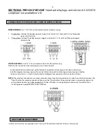
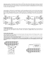
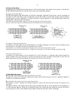
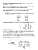
background image


14 


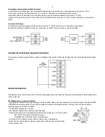
6) Connect safety devices 

Failsafe feature: A monitored failsafe safety feature is built into the operator. The operator has provisions to connect one 
primary monitored safety device as well as one or more non-monitored safety device(s). 
 

Primary monitored safety device: 

MICANAN monitored failsafe photo beams or MICANAN compatible monitored failsafe devices must be connected to 
terminals P1 and P2 if momentary close on pushbutton is required (B2 mode). If not connected, door can only be closed by 
constant pressure on close pushbutton.  If constant pressure on close pushbutton is removed before door reaches full 
closed position, then door reverses to full open. 

Note: Only one monitored failsafe safety device can be connected across terminals P1 and P2. 
Note: See section E for complete installation instructions for the Micanan N-1 or N-4 photocells. 


Secondary non-monitored safety device(s): 

A standard 2-wire safety edge, non-monitored reflective or thru-beam photo eye or any other non-monitored reversing 
devices with a N.O dry contact can be connected to terminals S1 and S2. 

Note: More than one secondary non-monitored safety device can be connected to terminals S1 and S2.  
Important: Do not remove resistor that is factory installed across terminals S1 and S2 unless installing a 4-wire electric edge. 


4-wire electric edge Connection 

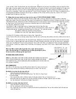
A standard 4-wire electric edge can be connected across S1 and S2 terminals as a secondary safety device. Remove the 
factory installed resistor across terminals S1 and S2 and install resistor across the black and white pair of wires from the 
electric edge and connect the remaining black and white wire to the S1 and S2 terminals. 


7) Select Mode of Operation:  

C2

 mode of operation (momentary on open, constant pressure on close): 

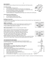
The operator is wired at the factory for momentary on open and constant pressure on close. For commercial operators, 
white wire is connected to terminal T6.  
 

B2

 mode of operation (momentary on open, momentary on close):  

If momentary on close is required: For commercial operators, remove the white wire from terminal T6 and place it on 
terminal T3.  
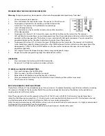
The operator functions in B2 mode only when the primary monitored safety device is connected and functioning properly. If 
it is not connected, operator will go into fault mode and door can only be closed by constant pressure on close and if 
constant pressure on close is removed before door reaches full close position, door reverses to full open.


Содержание PRO-GH

Страница 1: ...INSTALLATION AND INSTRUCTION MANUAL MODELS PRO GH PRO GHC AUG 2010...

Страница 2: ...0 OPERATOR MAINTENANCE ____________________________________________________ 31 MECHANICAL DRAWINGS AND PARTS LISTS _____________________________________ 32 ELECTRICAL DIAGRAMS ________________________...

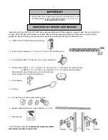
Страница 3: ...x Door Sprocket 50B23 x 1 or 1 1 4 bore 2 set screws and x 1 1 4 keyway for sectional doors or 50B40 x 1 or 1 1 4 bore 2 set screws and x 1 1 4 keyway for rolling doors Note Sprocket size and bore ma...

Страница 4: ...rd Smart 10 0 UL325 2010 compliant Note Micanan compatible primary entrapment device must be connected for B2 T or TS momentary or timer activation on close feature Option 2 Relay logic controls with...

Страница 5: ...door system READ AND FOLLOW ALL INSTALLATION INSTRUCTIONS Commercial door operators are never to be installed on a residential installation Install only on a properly operating and balanced door A doo...

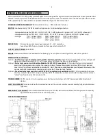
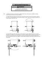
Страница 6: ...on opposite side of drive shaft For both the PRO GH and PRO GHC operators the handing of the operator should be stated at time of order Depending on installation if handing of chain hoist is not corre...

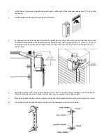
Страница 7: ...shaft is approximately 12 30cm to 15 38cm The operator may be wall bench mounted or bracket shelf mounted These two mounting configurations are shown below 4 Mount the operator to the wall hood or be...

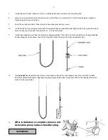
Страница 8: ...s floor Cut chain and connect so that chain is 2 to 3 from the floor 11 Install chain keeper to wall near hand chain at approximately 4 from floor Run disconnect chain through keyhole of chain keeper...

Страница 9: ...10V WW MSL100 220V WW MSLC100 WW MSL300 WW or MSLC300 WW in the electrical drawings section at the end of this manual Refer to electrical diagrams inside control box cover or at the end of this manual...

Страница 10: ...moving parts of door or hardware Install Entrapment warning sign next to control station Connect 3 button open close stop push button station to terminals 2 3 4 and 5 Refer to electrical diagram for c...

Страница 11: ...iver Wire standard radio receiver to separate radio strip on side of control box or to terminals 7 8 and 9 on control terminal strip inside control box 4 Single button open close device Wire to termin...

Страница 12: ...le phase or 3 phase Connect open close stop push button station to terminals T2 stop T3 common T4 open and T6 temporary CP on close 3 Verify motor direction After the electrical power connections are...

Страница 13: ...imits Remove blue wire from advanced open limit and place it on N O pin of advanced close limit 4 Adjust limit switch cams Using the open close stop push button station move door to fully closed and f...

Страница 14: ...fety device can be connected to terminals S1 and S2 Important Do not remove resistor that is factory installed across terminals S1 and S2 unless installing a 4 wire electric edge 4 wire electric edge...

Страница 15: ...inal strip must remain connected MOTOR DIRECTION VERIFICATION Make sure the mode of operation is selected to D1 After electrical power connections are made manually move door to mid position Using the...

Страница 16: ...irection have been verified adjust the limit cam settings Please note that when each limit switch is activated the corresponding LED will light up Refer to operator installation manual for complete li...

Страница 17: ...ernal single button as shown in diagram Please refer to Modes of operation for the functionality of single button MODES OF OPERATION All operators leave the factory in the D1 mode setting please read...

Страница 18: ...Momentary contact from mid stop opens the door to full open position Constant activation when door is opening bypass mid stop if enabled Close button Constant pressure on close Door reverses to full o...

Страница 19: ...ivation reverses the door Momentary activation refreshes the timer to close Timer to close Closes the door from mid stop or full open Momentary activation of stop button will de activate the timer Tim...

Страница 20: ...ted in C2 D1 E2 and T modes of operation Delay on close timer is OFF when the Delay on close dial is set to OFF position To adjust this timer rotate the dial clockwise to the desired value The minimum...

Страница 21: ...itter Repositioning antenna may provide greater range 8 Repeat transmitter programming steps for additional transmitters OPERATION 1 Press and release the button on MICANAN transmitter 2 Receiver LED...

Страница 22: ...LED Status Cause Fault ON Primary safety devices not connected to P1 P2 or not functioning properly Safety devices are activated 10k Ohm resistor between S1 S2 removed or faulty Fault Blinking Interlo...

Страница 23: ...eversing door when door is almost fully closed To adjust door travel 1 Open cycle Depress cam plate and spin Open limit cam away from Open limit switch to increase door travel or spin Open limit cam t...

Страница 24: ...eam disconnect all power to door operator to prevent unintended operation and have the door full open or close 4 Do not reconnect power to the door or gate operator until instructed to do so 5 Only in...

Страница 25: ...nnect these paired wires to the P1 and P2 terminals on the logic board or interface module if applicable as shown in Figure 3 Use minimum 18 gauge wires and secure the wires to wall or ceiling MICANAN...

Страница 26: ...gning the photo beams 1 Turn the power on to the operator If the transmitter and receiver are installed properly the lights on both the transmitter red L E D and receiver green L E D will be ON 2 If t...

Страница 27: ...ting Nut make sure to secure input shaft to not allow shaft to rotate when tightening or loosening nut 4 Gradually tighten clutch nut until the tension is sufficient to permit clutch to drive door smo...

Страница 28: ...e with operator drive chain Slide stabilizing rod through slot of engagement arm and attach to frame or external support to prevent arm from rotating during operation Note Location of arm and stabiliz...

Страница 29: ...o decrease nylon lock nut on brake spring bolt Observe solenoid during electrical testing of brake Brake spring tension must be adjusted so that solenoid should pull and release smoothly and quietly T...

Страница 30: ...f operator is supplied with optional floor level disconnect lever Pull disconnect lever downwards and lock in place by bending lever around bracket lip as shown 3 Operate door by pulling on hand chain...

Страница 31: ...5 Verify that motor solenoid and operator runs smoothly and quietly Every 6 months 1 Verify tightness of all fasteners and set screws 2 Verify that operator is properly secured 3 Inspect manual disco...

Страница 32: ...32...

Страница 33: ...33 33...

Страница 34: ...34...

Страница 35: ...35 35...

Страница 36: ...36 36...

Страница 37: ...37...

Страница 38: ...38...

Страница 39: ...39...

Страница 40: ...40...

Страница 41: ...41...

Страница 42: ...42...

Страница 43: ...43...

Страница 44: ...44...

Страница 45: ...hat materials and workmanship are free from defects for a period of two years from the date of invoice Materials returned to Micanan deemed defective after examination will be returned at the option o...

Отзывы: