background image

17.3.2005

 Rev.  2.0

Adjustment instructions

21

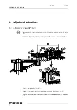
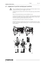
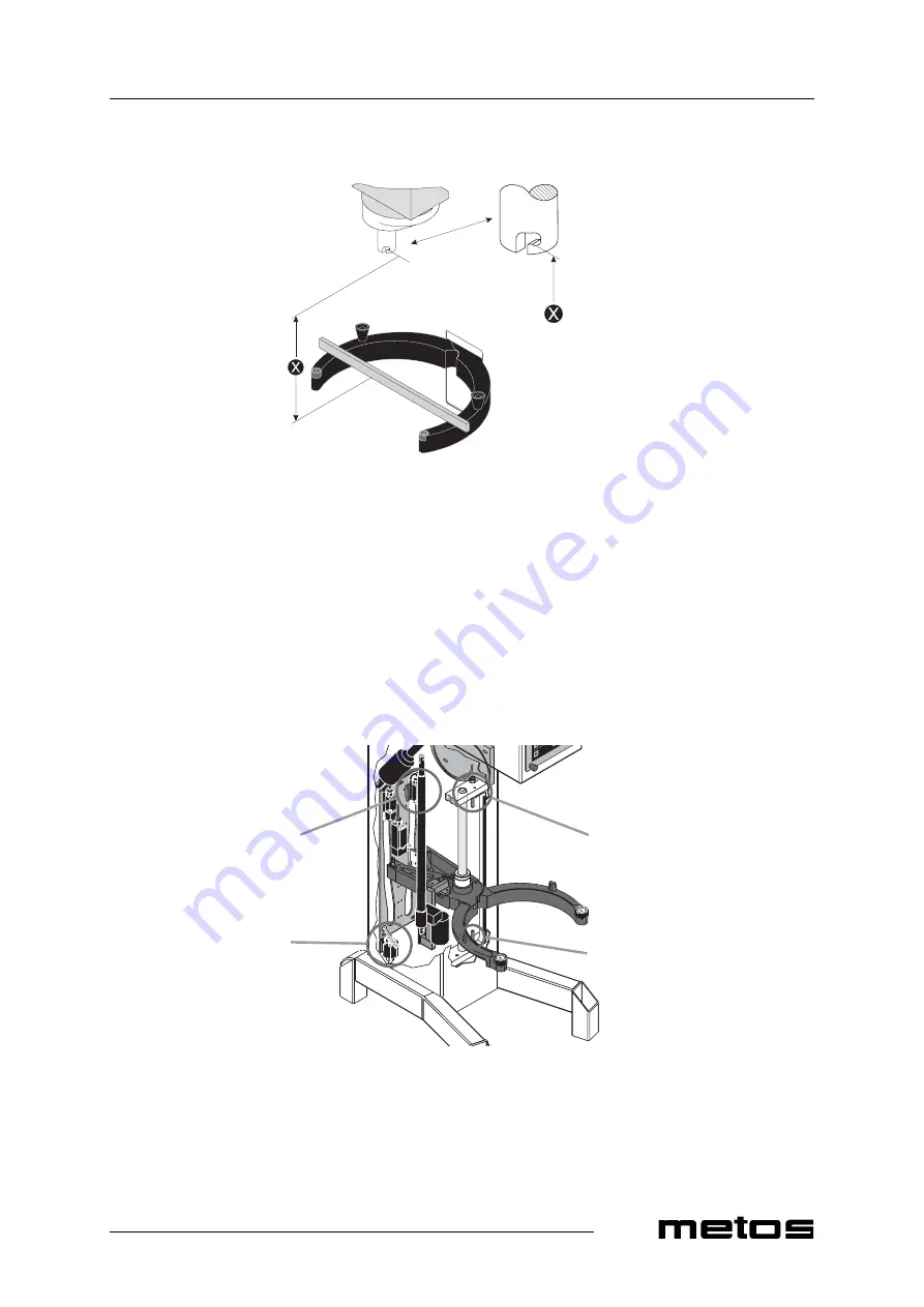
Bowl height (X): AE40 = 162 mm

The upper and lower position of the bowl is determined by microswitch (1) and (2),
(Fig.6). The two mechanical stops consisting of the bolts (3) and (4) are adjusted so that
they will be hit approx. 2 mm after the microswitch, in case the microswitch should
fail.The upper position of the bowl arms is adjusted by moving the microswitch (1) in its
slots, it is of utmost importance that the stop screw (3) is readjusted afterwards. In the
same way the lower position is adjusted by moving the microswitch (2) in its slots. there-
after the mechanical stop (4) is adjusted.

)LJ

)LJ

Содержание AE40 Series

Страница 1: ...MIXER VL3 TYPE AE40 Installation and Operation Manual S N Rev 2 0...

Страница 2: ......

Страница 3: ...ppliance The instructions and hints in this manual will give you a quick and easy start and you will soon note how nice it is to use the Metos equipment All rights are reserved for technical changes Y...

Страница 4: ...17 3 2005 Rev 2 0 2...

Страница 5: ...xer 11 4 1 3 Four fixed speeds 11 4 1 4 Indication of operation time 11 4 1 5 Automatic lowering of bowl 11 4 1 6 Inspection of the ingredients during operation 11 4 1 7 Lowering of bowl 12 4 1 8 JOG...

Страница 6: ...Adjustment of bowl fixing 20 6 4 Adjustment of bowl height 20 6 5 Adjustments of speed low and high speed cam disks 22 6 6 Exchange of control panel 23 6 7 Exchange of emergency stop in control panel...

Страница 7: ...r and using original spare parts Not complying with the above may put the safety of the appliance in danger The manufacturer does not take responsibility for any damages in case the operation in struc...

Страница 8: ...17 3 2005 Rev 2 0 General 2 resentative When ordering new manuals it is essential to quote the serial number shown on the rating plate...

Страница 9: ...s in the bowl while the mixer is running may cause injuries 2 1 Safety instructions in case of malfunction Before any service operations the appliance must be disconnected from the electric net work 2...

Страница 10: ...the mixer is running the chosen operation time is reset and the speed is set to minimum The same when pushing emergency stop The operation time and speed can be changed while the mixer is running The...

Страница 11: ...There is a power connection to the mixer and the bowl is not in its top position The bowl can be raised by activating the fields time down time up and bowl up simultaneous ly diodes in the fields are...

Страница 12: ...on time can be chosen by activating the fields time down time up The bowl can be lowered by activating the field bowl down The mixer is ready for operation by activating the field Start Stop The bowl...

Страница 13: ...field time up green diode in the field Start Stop is flashing The mixer is running green diode in the field Start Stop is constantly alight when the chosen sped has been reached The operation time ca...

Страница 14: ...on 8 The safety guard has been opened while the mixer was running When the safety guard is closed the control panel shows Pos 2 The emergency stop has just been released All settings are reset The con...

Страница 15: ...l can be lowered by activating the field bowl down The mixer can be started by activating the field Start Stop The mixer runs and operation time has been indicated Automatic lowering of bowl at ended...

Страница 16: ...up simultaneous ly the activation to be continued until the bowl has reached its top position When the bowl is approx 10 cm from its top position the tool will start to rotate in low speed The rotati...

Страница 17: ...up If the field is activated for longer time the speed is increased reduced quicker Minutes and seconds are shown in the text field between time down and time up 4 1 5 Automatic lowering of bowl When...

Страница 18: ...yond the recommended values or if a wrong mixing tool is used large lumps of fat or cooled ingredients must be cut into small parts before they are placed in the bowl Prolonged overload will make the...

Страница 19: ...bowl is placed correctly in the bowl arms all the way back in the bowl arms the mix er can only be operated when the sensor is activated It is possible to lift the bowl arms even if the bowl is not mo...

Страница 20: ...st not be washed with strong alkaline detergents pH not bigger than 9 0 Whip Beater Hook Cream Cake dough Bread dough Egg whites Butter cream Dark bread and the like Mayonnaise and the like Waffle dou...

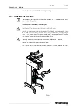
Страница 21: ...tart the mixer and increase the speed to approx 50 Stop the mixer and open the lid on the top of the mixer On the top of each of the two pulley set shafts is a grease nipple fig 3 point 1 Press grease...

Страница 22: ...he marked points with an oil can fig 3 point 2 4 2 3 Grease types Grease for the pulley set shafts Castrol LMX When repair of the planetary head grease the toothed wheel and the toothed rim with Cas t...

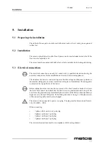
Страница 23: ...uency printed on the machine rating plate is correct in relation to the place of installation The rating plate is placed on the top right side of the mixer Before taking the mixer into use the movemen...

Страница 24: ...tch off the mixer by disconnecting the power cable The distance X is only indicative as it depends on the tolerance of the special V belt 1 Start by tightening the V belts 2 Tighten the special V belt...

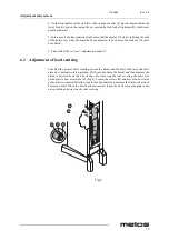
Страница 25: ...en follow the section Adjustment of speed 6 2 Adjustment of bowl centring First find the present bowl centring mount the beater and the bowl then raise the bowl arms up to normal working position With...

Страница 26: ...r points away from the bowl arms which means the tightest bowl clamping In case the bowl fastening is too tight remove the lock ring B and draw the bearing A from the shaft C Fig 4 The bearing should...

Страница 27: ...are adjusted so that they will be hit approx 2 mm after the microswitch in case the microswitch should fail The upper position of the bowl arms is adjusted by moving the microswitch 1 in its slots it...

Страница 28: ...the connection between servomotor and Inductive sensor At the back of the right bowl arm there is an indicative sensor Fig 1 which is activated when the bowl is placed correctly in the bowl arms all t...

Страница 29: ...activating of microswitch for minimum speed so that acoustic sound is heard but as close to turn off of acoustic signal as possible Start the mixer by activating the field Start Stop Turn the handle f...

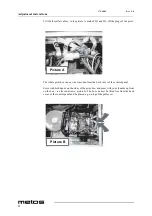
Страница 30: ...e whole print box can now be loosened from the back cover of the control panel Seize with both hands on the sides of the print box and press with your thumbs up front on the box see the red arrows pic...

Страница 31: ...remember to place the three flat cables in the correct plugs Then follow the instructions Calibration of control panel 6 7 Exchange of emergency stop in control panel When the control panel has been r...

Страница 32: ...ly The text field will now show Activate the fields 1 2 3 and 4 The text field will now show Activate the fields time down and time up simultaneously The mixer will automatically calibrate the control...

Страница 33: ...number of the unit and the date the unit has been installed a short description of the fault what function is not working what signals the dis plays are showing what happened was done immediately befo...

Страница 34: ...17 3 2005 Rev 2 0 Troubleshooting 28...

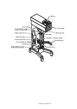
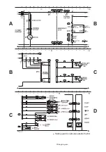
Страница 35: ...17 3 2005 Rev 2 0 Technical specifications 33 9 Technical specifications Construction AE40 VL3 AE40 VL3 Installation drawing Wiring diagram...

Страница 36: ...WKH ERZO DUPV 6DIHW VZLWFK 0LFUR VZLWFK IRU WKH XSSHU SRVLWLRQ RI WKH ERZO DUPV RZO OLIW PRWRU QGXFWLYH VHQVRU RZO OLIW DUPV 3ULQW ER 16 JXLGH ERZO DUP JXLGH SODWH 2 PLFUR VZLWFK 6HUYR PRWRU LWWLQJ IR...

Страница 37: ...AE40 VL3 Installation drawing...

Страница 38: ...Wiring diagram 6DIHW JXDUG LV RSWLRQDO RXWVLGH WKH 8...

Страница 39: ...17 3 2005 Rev 2 0 Technical specifications 37 3 VL3 40 AE40 Item Model Type Specification Capacity L VL3 AE40 40L...

Страница 40: ...DO VXSSOLHV GHWHUPLQHG ZLWKLQ FHUWDLQ YROWDJH OLPLWV ZLWK VSHFLDO UHIHUHQFH WR DSSHQGL WR WKH GLUHFWLYHV UHJDUGLQJ HVVHQWLDO VHFXULW DQG KHDOWK GHPDQGV LQ FRQQHFWLRQ ZLWK WKH FRQVWUXFWLRQ DQG SURGXFWL...

Отзывы: