17.3.2005
Rev. 2.0
Adjustment instructions
20
6.3
Adjustment of bowl fixing
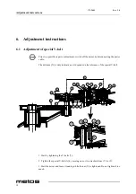
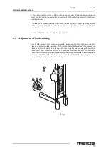
The bowl arms must be raised to normal working position. The adjustment diameter (Y)
shall be measured inside between the bowl arms (Fig.4a)
Adjusting diameter (Y): AE40 = 389 mm
The bearing (A) (Fig.4) has two diameters. As standard, a mixer is delivered with the bear-
ings mounted so that the largest diameter points away from the bowl arms, which means
the tightest bowl clamping.
In case the bowl fastening is too tight, remove the lock ring (B) and draw the bearing (A)
from the shaft (C) (Fig.4). The bearing should be turned 180° and be mounted on the shaft
again. it might be necessary to turn both bearings. At last check the bowl centring and if
necessary, adjust.
6.4
Adjustment of bowl height
The distance (X) is measured from the bottom side of the bayonet hole to the surface on
the bowl arms on which the bowl rests (Fig.5). The bowl arms must be lifted to normal
working position.
)LJD
Содержание AE40 Series
Страница 1: ...MIXER VL3 TYPE AE40 Installation and Operation Manual S N Rev 2 0...
Страница 2: ......
Страница 4: ...17 3 2005 Rev 2 0 2...
Страница 34: ...17 3 2005 Rev 2 0 Troubleshooting 28...
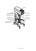
Страница 37: ...AE40 VL3 Installation drawing...
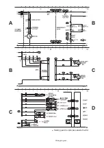
Страница 38: ...Wiring diagram 6DIHW JXDUG LV RSWLRQDO RXWVLGH WKH 8...

