


Copyright Meritor, Inc., 2021
MM-96147 / Revised 03-21
Page 87
(16579)
Printed in USA
14 Measuring and Recording Driveline Angles
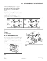
6. Repeat Step 5 for the carrier universal joint.
7. Using a carpenter’s square, measure the distance from the
transmission universal joint point to the frame rail reference
line. Figure 14.32.
4005554a
Fig. 14.32
8. Repeat Step 7 for the carrier universal joint.
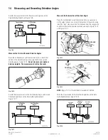
9. The universal joint plan view angle (true joint angles) can now
be calculated by using Formula 1.
Calculate Driveline Angles
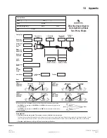
1. Measure and record the side view angles. Refer to the
procedure in this section. Figure 14.33 is shown as a
reference.
4005571a
TRANSMISSION
ANGLE
RIGHT AXLE
ANGLE
JOINT 2 ANGLE
JOINT 1 ANGLE
DRIVELINE
ANGLE
1.0
2.0
3.0
-1.0
-1.0
Fig. 14.33
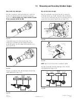
2. Calculate the plan view universal joint angles using Formula 1.
Figure 14.34.
4005555a
Formula 1
Driveline_Length
Distance
Trans
–Distance
A
xle
Plan_
A
ngle= Tan
–1
(
)
Fig. 14.34
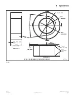
4005572b
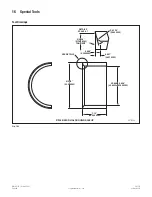
DRIVELINE LENGTH
(CENTER TO
CENTER)
TR
A
NSMISSION
JOINT OFFSET
(CENTER TO
FR
A
ME R
A
IL)
(DIST
A
NCE TR
A
NS)
A
XLE JOINT
OFFSET
(CENTER TO
FR
A
ME R
A
IL)
(DIST
A
NCE
A
XLE)
FR
A
ME R
A
IL
Fig. 14.35
NOTE:
Both joints will have the same plan view angle. Figure 14.35
is shown as a reference.
3. Calculate the compound universal joint angles using
Formula 2. Figure 14.36.
4005555c
Formula 2
Side_
A
ngle
2
+ Plan_
A
ngle
2
Compound_
A
ngle =
from Step 1
from Step 2
Fig. 14.36
The compound universal joint angles (true universal joint operating
angles) should not be greater than 5 degrees during vehicle
operation, and the difference between the carrier-driveline joint
angle and transmission-driveline joint angle should not be greater
than 1.5 degrees to ensure optimal operation of the drivetrain.