


Copyright Meritor, Inc., 2021
MM-96147 / Revised 03-21
Page 53
(16579)
Printed in USA
8 Easy Service
Lubrication
Universal Joint
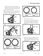
Lubricate the universal joints at the grease fi tting until grease fl ows
from the bearing cup seals on all four trunnions. Use a grease
that meets Meritor specifi cation O-634-B, NLGI Grade 2 with EP
additive. Figure 8.11.
• If grease does not purge from all four trunnion seals:
Follow the steps below.
a. Move the assembly UP-AND-DOWN or SIDE-TO-SIDE
while you apply grease gun pressure. Figure 8.12.
b. Loosen the bearing cup capscrews. Add grease until
grease purges from the four seals.
c. Tighten the bearing cup capscrews after grease purges.
• If grease still does not purge from all four trunnion
seals:
Remove the universal joint and correct the problem.
If you cannot, replace the universal joint.
New grease must
flow at all four seals.
4001852a
Fig. 8.11
4001853a
Fig. 8.12
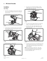
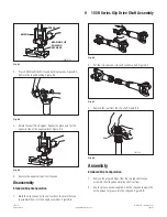
Slip Yoke Splines
NOTE:
When you lubricate a slip yoke, the splined shaft can be
either fully extended or fully collapsed.
Add a grease that meets Meritor specifi cation O-634-B, NLGI
Grade 2 with EP additive, to the slip yoke grease fi tting. Six to eight
pumps or approximately one oz (28 grams) is suffi cient to lube the
splines. Figure 8.13.
4001847a
Fig. 8.13