


Copyright Meritor, Inc., 2021
MM-96147 / Revised 03-21
Page 33
(16579)
Printed in USA
5 RPL Series Permalube
4001817c
Fig. 5.60
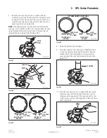
Strike the yoke ear with a brass or copper hammer to ensure that
the universal joint moves freely. Figure 5.61.
Move the joint with your hand
to ensure free movement.
4001818c
Fig. 5.61
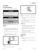
Driveline
WARNING
If you do not correctly install the universal joint and end yoke, the
bushings will not correctly seat in the yoke, which can cause the
capscrews that secure the universal joint to fatigue under normal
operating conditions. Serious personal injury and damage to
components can result.
WARNING
You must position the wing bushing’s machined keyway against
the machined keyway of the end yoke ears when you install
a universal joint. Ensure that the arrows stamped on the wing
bushing point TOWARD the end yoke, and the universal joint
weld strap faces the driveline and AWAY from the yoke.
CAUTION
A broken weld strap can cause a wing bushing to rotate. When
a bushing rotates, it’s possible to assemble it into the yoke
backward. To ensure correct assembly and prevent damage
to components, you must insert both of the wing bushing’s
machined keyways into the yoke.
1. Before you install the capscrews, check that the universal
joint is fully seated in the end yoke. The arrows on the wing
bushing should point toward the coupling yoke. Figure 5.62.
4001836b
Machined keyways
are on this side.
WELD STRAP
Arrows toward
coupling yoke.
Fig. 5.62
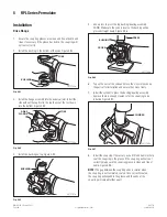
2. If necessary, tap the universal joint with a brass or copper
hammer to ensure it is fully seated. Figure 5.63.
4001891b
Machined
keyways
are on
this side.
WELD STRAP
YOKE NIBS
Arrows indicate
direction of
installation.
Fig. 5.63
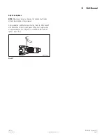
NOTE:
Any time a universal joint is disconnected, new capscrews
must be used during reassembly.
3. Install the new capscrews.
4. Use a torque wrench to alternately tighten the capscrews to
115-135 lb-ft (155-183 Nm). Figure 5.64.