


Copyright Meritor, Inc., 2021
MM-96147 / Revised 03-21
Page 63
(16579)
Printed in USA
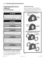
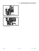
10 Center Bearing Removal and Installation
Fig. 10.10 Yoke-Style Driveline
4011836a
Fig. 10.11 Flange-Style Driveline
6. Inspect the center bearing end yoke or fl ange splines.
• If the splines are damaged or missing, or the yoke or
fl ange is cracked:
Replace the yoke or fl ange.
7. Inspect the coupling shaft splines and threads.
• If the splines or threads are damaged or missing:
Replace the entire coupling shaft.
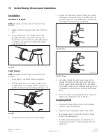
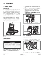
Center Bearing
1. Remove and discard the center bearing bracket. Figure 10.12.
CENTER
BEARING
BRACKET
Fig. 10.12
2. Remove and discard the rubber cushion. Figure 10.13.
Fig. 10.13
3. Use a puller to remove the bearing assembly from the
coupling shaft. Follow the puller tool manufacturer’s
instructions. Discard the center bearing. Figure 10.14.
Fig. 10.14
4. Inspect the coupling shaft for wear on the bearing diameter.
• If the coupling shaft is damaged from a seized
bearing:
Replace the entire coupling shaft. Figure 10.15.
BEARING
DIAMETER
Fig. 10.15
NOTE:
Self-aligning center bearings do not require external
defl ectors.
5. Remove both defl ectors, if equipped. Install a new center
bearing, defl ectors, if necessary, and coupling yoke.