


Copyright Meritor, Inc., 2021
MM-96147 / Revised 03-21
Page 45
(16579)
Printed in USA
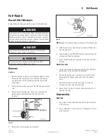
6 Full-Round
LARGE
DIAMETER
SMALL
DIAMETER
SHROUD
4001829a
Fig. 6.9
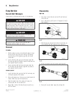
3. Install the slip shaft into the slip yoke. Ensure that you
reassemble the sections into their original positions by using
the marks made during disassembly. Figure 6.10.
4006701a
Fig. 6.10
4. Install the seal onto the groove in the slip yoke. Figure 6.10.
4001820a
Fig. 6.11
5. Snap the shroud over the seal.
Universal Joint
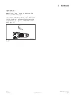
WARNING
Use a brass or synthetic mallet for assembly and disassembly
procedures. NEVER hit steel parts with a steel hammer. Pieces
of a part can break off. Serious personal injury and damage to
components can result.
1. Install the universal joint cross into the yoke.
2. Install the two bearing cups through the yoke bores and onto
the universal joint cross trunnions. If necessary, use a copper
or brass hammer to tap the bearing caps until they are fully
seated.
3. Hand-tighten the capscrews through the bearing cover plate
and into the slip yoke.
4. Use a torque wrench to alternately tighten the capscrews to
the correct specifi cations. Refer to Table B.
5. Repeat Step 1 to Step 3 to install the universal joint cross into
the weld yoke.
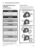
Driveline
1. Wipe off the end yoke bearing bores. Insert the trunnion
through the yoke bore.
2. Check the bearing cup to ensure that the needle bearings are
in place. Replace the bearing cup when the needle bearings
are missing or out of place.
3. Hold the cross. Use a copper or brass hammer to lightly tap
the bearing cup completely into the yoke bore. Figure 6.12.
4001840a
Fig. 6.12
4. Align the cover plate holes and the yoke ear. Figure 6.13.
Install the bearing cover plate fl ush against the milled surface
of the yoke.
CAPSCREWS
4001841a
Fig. 6.13