


Copyright Meritor, Inc., 2021
MM-96147 / Revised 03-21
Page 41
(16579)
Printed in USA
5 RPL Series Permalube
4011770a
SNAP
RING
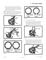
Fig. 5.98
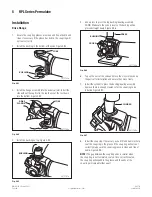
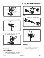
9. Rotate the assembly 180 degrees (turn it over). Figure 5.99.
4011771a
BUSHING
Fig. 5.99
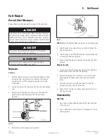
10. Install the cylinder and press down to create clearance for
snap ring installation. Figure 5.100.
4011772a
CYLINDER
Fig. 5.100
11. Install the snap ring. If necessary, use a drift and hammer
(suitable tool and mallet) to seat the snap ring in the groove. If
the snap ring will not seat correctly, make sure the snap ring
groove is clean and free of debris.
12. After assembly, strike the ears of the yoke with a brass mallet
to relieve the stress and free up the cross joint. Move it by
hand to ensure it moves freely.
Coupling Joint Flange
1. Use a suitable fi xture or method to immobilize the drive fl ange
end so the coupling joint end will not rotate.
2. Install the coupling joint fl ange onto the driveline.
3. Install the nut on the coupling joint fl ange.
4. Use a socket to tighten the nut to 450-600 lb-ft (610-813 Nm).
Driveline
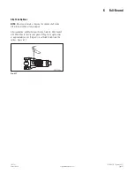
1. Raise the driveline and position it to the vehicle.
2. Align the driveline drive fl ange to the vehicle input drive
fl ange according to the reference marks made during
removal. The driveline must be reinstalled with the same
phasing. Figure 5.101.
4011752b
DRIVESHAFT
REFERENCE
MARKS
DRIVE
FLANGE
Fig. 5.101
NOTE:
Any time the universal joint is disconnected, new bolts,
washers and nuts from kit KT35BNW must be used during
reassembly.
3. Install the new bolts, washers and nuts to secure the drive
fl ange to the input drive fl ange. Tighten the nuts to
133-163 lb-ft (180-220 Nm). Figure 5.102.
4011752e
BOLT
NUT
WASHER
Fig. 5.102