


Copyright Meritor, Inc., 2021
MM-96147 / Revised 03-21
Page 84
(16579)
Printed in USA
14 Measuring and Recording Driveline Angles
NOTE:
You must correctly enter information in Step 2 through
Step 5 to obtain a correct analysis. If fi elds are left blank, you will
not obtain an analysis.
2. Enter the maximum engine RPM. Figure 14.24.
3. Enter the transmission overdrive ratio. This value should be
less than 1. For direct drive applications,
enter 1. Figure 14.24. Click the
Select By Vendor
pull-down
menu. Click on the
GO
button. The screen will display lists of
transmissions by manufacturer. You can select your specifi c
transmission model and ratio from these lists.
NOTE:
The phasing type is not required for angle analysis of one-
piece driveline confi gurations.
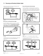
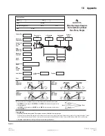
4. Enter the driveline phasing type. Click on the
VIEW
button
next to the
Phasing Type
fi eld to view examples of the four
phasing types. Figure 14.25. Passing the cursor over the
example windows will close them.
4001913b
Fig. 14.25
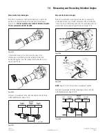
NOTE:
Each driveline section is designated either PARALLEL or
CROSSED, which is determined by the position of the yokes at
either end of the section. If the yoke lugs on the two yokes are
aligned, the section is PARALLEL.
If the yoke lugs are not aligned (opposite or crossed), the section
is CROSSED. Both sections are considered when determining the
phasing type.
Common driveline phasing types are: Figure 14.26.
• Type 1: Parallel-Parallel
• Type 2: Crossed-Parallel
• Type 3: Parallel-Crossed
• Type 4: Crossed-Crossed