


MA-5162-ENG
PISTON ADHESIVE MELTER
MELTER OPERATION
4-1
4. MELTER OPERATION
In this section we will introduce the method for using the melter. Although its
operation is very simple, it should not be used by untrained personnel.
Warning
: Improper use may cause damage to the machine or injury and even
death to the person using it.
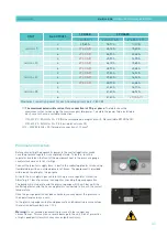
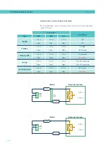
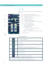
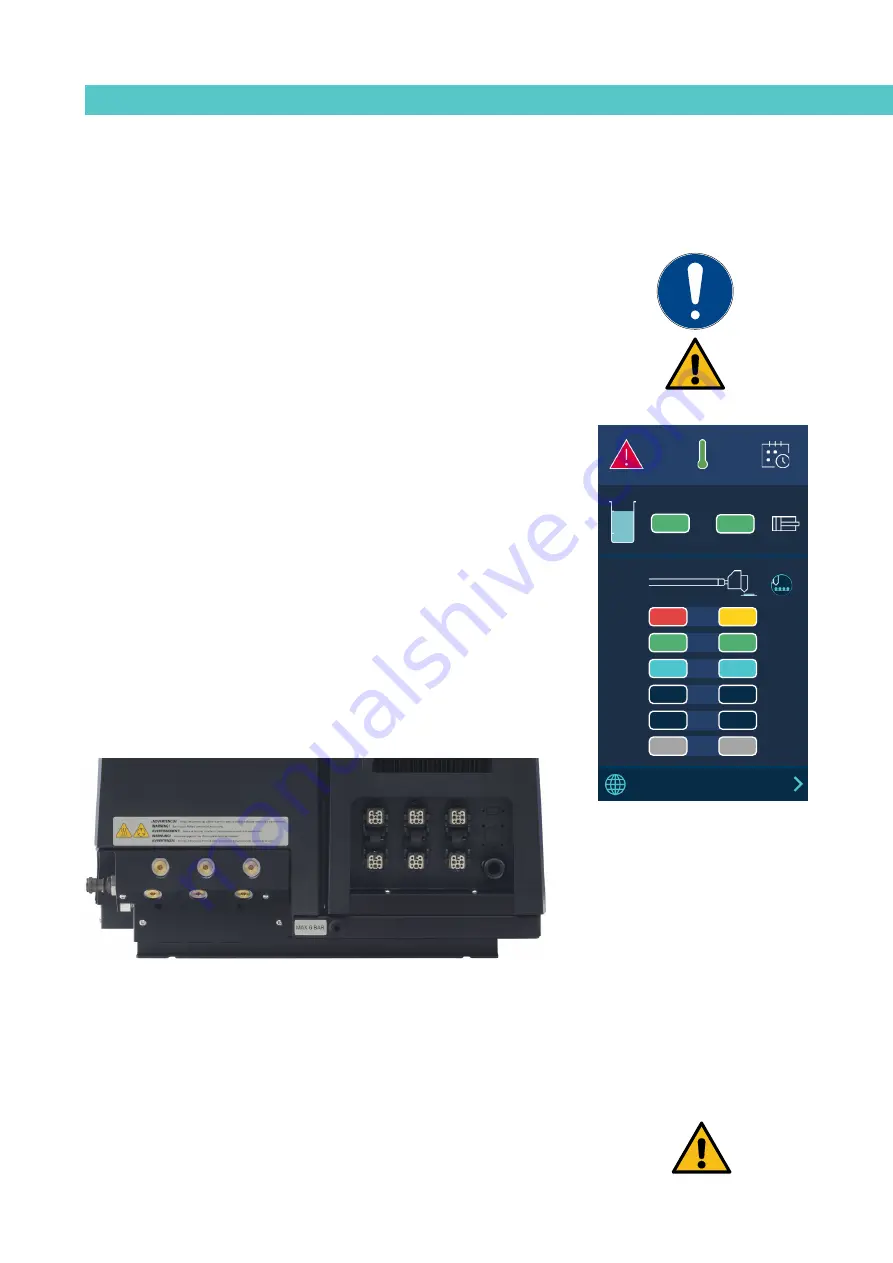
General information
There are three large groups of components with thermal control in a hot-
melt installation: the fusion unit, the transport hoses and the applicators. All
of these are controlled from the front panel of the melter equipment.
The first large group is the tank (T) an distributor (D) group and they have
separate programmable controls.
The second group is the hose group. They are identified on the front panel,
depending on the equipment model, by number, from number 1.1 to number
6.1 . Each one has its own set point value.
The third group is the applicators group. It is identified on the front panel,
depending on the equipment model, by number from number 1.2 to number
6.2 . Each one has its own set point value.
The hose and applicator numbers are automatically assigned to the hose/
applicator channel they are connected to on the rear part of the melter.
PISTÓN
HMI
: S02001101 v1.1.2
TC
: S02200100 v1.0.84
IO FM : XXXXXXXXX vx.x.x
154
154
A
15:35
°C
08:31
185
170
1
154
154
2
100
100
3
---
---
4
5
42
42
6
B
1
2
3
4
5
6
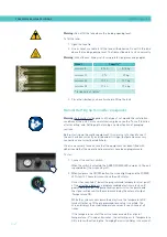
Filling the tank
The tank can be equipped with a low level capacitive sensor that warns when the
level of hot-melt adhesive drops below a third of the tank’s capacity.
The unit will deactivate the external signal and, if it is connected, will activate its
the corresponding warning device.
Warning
: Before refilling the tank, make sure that the adhesive is the same type
as that already in the tank. Mixing different types of adhesives can cause damage
to the melter equipment.
Содержание Micron + 10
Страница 10: ...FOCKE MELER GLUING SOLUTIONS TABLE OF CONTENTS This page is intentionally left blank ...
Страница 38: ...FOCKE MELER GLUING SOLUTIONS INSTALLATION 3 16 This page is intentionally left blank ...
Страница 74: ...FOCKE MELER GLUING SOLUTIONS 4 36 MELTER OPERATION This page is intentionally left blank ...
Страница 84: ...FOCKE MELER GLUING SOLUTIONS 5 10 MAINTENANCE This page is intentionally left blank ...
Страница 90: ...FOCKE MELER GLUING SOLUTIONS 6 6 TECHNICAL CHARACTERISTICS This page is intentionally left blank ...
Страница 91: ...MA 5162 ENG MICRON PISTON ADHESIVE MELTER ELECTRICAL DRAWINGS 7 1 7 ELECTRICAL DRAWINGS ...
Страница 92: ...FOCKE MELER GLUING SOLUTIONS 7 2 ELECTRICAL DRAWINGS This page is intentionally left blank ...
Страница 97: ...MA 5162 ENG MICRON PISTON ADHESIVE MELTER PNEUMATIC DIAGRAM 8 5 Pneumatic diagram for 19 cm3 stroke PUMP ...
Страница 102: ...FOCKE MELER GLUING SOLUTIONS 8 10 PNEUMATIC DIAGRAM This page is intentionally left blank ...
Страница 104: ...FOCKE MELER GLUING SOLUTIONS 9 2 SPARE PARTS LIST This page is intentionally left blank ...
Страница 118: ...This page is intentionally left blank ...