then calculate the measurement range. This is the range of
measurement over which the error in service is less than 30%
of the reading. Digital instruments are affected by the number
of digits error – for example a value 0,10
Ω
measured with the
continuity range may give a display in the range 0,07
Ω
to
0,13
Ω
which is a maximum error of 30%. Therefore the
measurement range measuring low resistance is 0,10
Ω
to
99,9
Ω
. When checking that a measurement does not exceed a
limit, the service error needs to be taken into account and
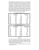
these tables enables this to be done quickly and easily. These
will guarantee that the value being measured is greater than or
less than the limit value specified as appropriate.
Insulation Resistance – M
Ω
Limit
Min.Indicated
Limit
Min.Indicated
Reading
Reading
0,10
0,14
2,00
2,12
0,20
0,25
3,00
3,16
0,30
0,35
4,00
4,20
0,40
0,46
5,00
5,24
0,50
0,56
10,00
10,8
0,60
0,66
20,00
21,2
0,70
0,77
30,00
31,6
0,80
0,87
40,00
42,0
0,90
0,98
50,00
52,4
1,00
1,08
100,00
94,0
Continuity Resistance –
Ω
Limit
Max. Indicated
Limit
Max. Indicated
Reading
Reading
0,10
0,06
2,00
1,88
0,20
0,15
3,00
2,84
0,30
0,25
4,00
3,80
0,40
0,34
5,00
4,76
0,50
0,44
10,00
9,56
0,60
0,54
20,00
18,8
0,70
0,63
30,00
28,4
0,80
0,73
40,00
38,0
0,90
0,82
50,00
47,6
1,00
0,92
100,00
92,0
SAFETY
The instruments meet the requirements for double insulation to
IEC 1010-1 (1995), EN 61010-1 (1995) to Category III*, 300V
phase to earth (ground) and 500V phase to phase, without the
need for separately fused test leads. If required, fused test leads
are available as an optional accessory.
* Relates to the transient overvoltages likely to be met in fixed
wiring installations.


