background image

Safety Instructions

Safety Instructions • English

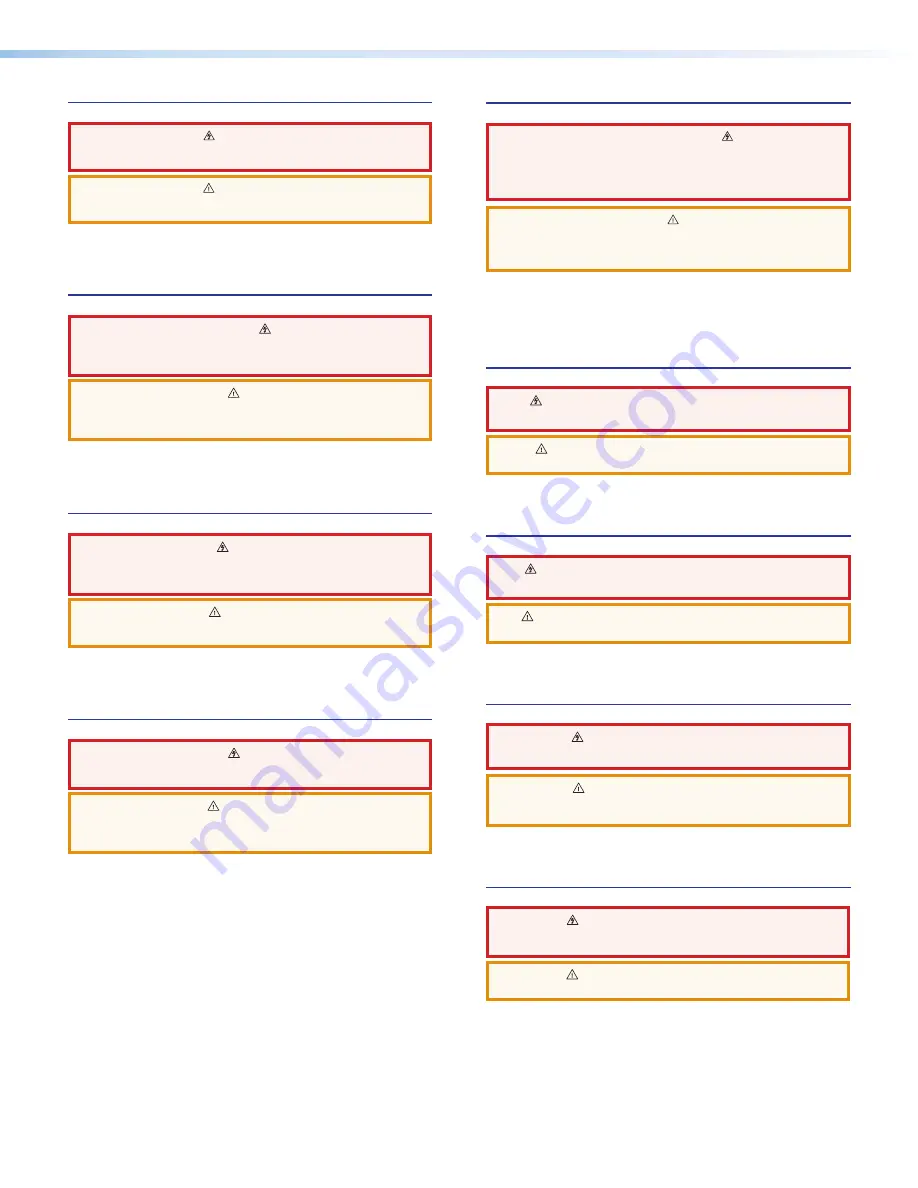
WARNING: 

This symbol, 

, when used on the product, is intended to 

alert the user of the presence of uninsulated dangerous voltage within the 

product’s enclosure that may present a risk of electric shock.

ATTENTION: 

This symbol, 

, when used on the product, is intended 

to alert the user of important operating and maintenance (servicing) 

instructions in the literature provided with the equipment.

For information on safety guidelines, regulatory compliances, EMI/EMF 

compatibility, accessibility, and related topics, see the Extron Safety and 

Regulatory Compliance Guide, part number 68-290-01, on the Extron website, 

www.extron.com.

Instructions de sécurité • Français

AVERTISSEMENT : 

Ce pictogramme, 

, lorsqu’il est utilisé sur le 

produit, signale à l’utilisateur la présence à l’intérieur du boîtier du produit 

d’une tension électrique dangereuse susceptible de provoquer un choc 

électrique.

ATTENTION : 

Ce pictogramme, 

, lorsqu’il est utilisé sur le produit, 

signale à l’utilisateur des instructions d’utilisation ou de maintenance 

importantes qui se trouvent dans la documentation fournie avec le 

matériel.

Pour en savoir plus sur les règles de sécurité, la conformité à la réglementation, 

la compatibilité EMI/EMF, l’accessibilité, et autres sujets connexes, lisez les 

informations de sécurité et de conformité Extron, réf. 68-290-01, sur le site 

Extron, 

www.extron.com

.

Sicherheitsanweisungen • Deutsch

WARNUNG:


Dieses Symbol 

 auf dem Produkt soll den Benutzer 

darauf aufmerksam machen, dass im Inneren des Gehäuses dieses 

Produktes gefährliche Spannungen herrschen, die nicht isoliert sind 

und die einen elektrischen Schlag verursachen können.

VORSICHT:


Dieses Symbol 

 auf dem Produkt soll dem Benutzer in der 

im Lieferumfang enthaltenen Dokumentation besonders wichtige Hinweise 

zur Bedienung und Wartung (Instandhaltung) geben.

Weitere Informationen über die Sicherheitsrichtlinien, Produkthandhabung,  

EMI/EMF-Kompatibilität, Zugänglichkeit und verwandte Themen finden Sie in 

den Extron-Richtlinien für Sicherheit und Handhabung  (Artikelnummer  

68-290-01) auf der Extron-Website, , 

www.extron.com

.

Instrucciones de seguridad • Español

ADVERTENCIA: 

Este símbolo, 

, cuando se utiliza en el producto, 

avisa al usuario de la presencia de voltaje peligroso sin aislar dentro del 

producto, lo que puede representar un riesgo de descarga eléctrica.

ATENCIÓN: 

Este símbolo, 

, cuando se utiliza en el producto, avisa 

al usuario de la presencia de importantes instrucciones de uso y 

mantenimiento recogidas en la documentación proporcionada con el 

equipo.

Para obtener información sobre directrices de seguridad, cumplimiento 

de normativas,  compatibilidad electromagnética, accesibilidad y temas 

relacionados, consulte la  Guía de cumplimiento de normativas y seguridad de 

Extron, referencia 68-290-01, en el sitio Web de Extron, 

www.extron.com

.

Инструкция по технике безопасности 

 Русский

ПРЕДУПРЕЖДЕНИЕ: 

Данный символ, 

, если указан 

на продукте, предупреждает пользователя о наличии 
неизолированного опасного напряжения внутри корпуса 
продукта, которое может привести к поражению 
электрическим током.

ВНИМАНИЕ:  

Данный символ, 

, если указан на продукте, 

предупреждает пользователя о наличии важных инструкций 
по эксплуатации и обслуживанию в руководстве, 
прилагаемом к данному оборудованию.

Для получения информации о правилах техники безопасности, 
соблюдении нормативных требований, электромагнитной 
совместимости (ЭМП/ЭДС), возможности доступа и других 
вопросах см. руководство по безопасности и соблюдению 
нормативных требований Extron на сайте Extron: 

www.extron.com

номер по каталогу - 68-290-01.

安全说明


简体中文


警告

产品上的这个标志意在警告用户该产品机壳内有暴露的危险 电压,

有触电危险。

注 意

产 品 上 的 这个 标 志 意 在 提 示用 户设 备 随 附 的用 户手 册 中 有 

重要的操作和维护(维修)说明。

关于我们产品的安全指南、遵循的规范、EMI/EMF 的兼容性、无障碍 
使用的特性等相关内容,敬请访问 

Extron 

网站 

www.extron.com

,参见 

Extron

 安全规范指南,产品编号 

68-290-01

安全記事


繁體中文


警告

若產品上使用此符號,是為了提醒使用者,產品機殼內存在著


可能會導致觸電之風險的未絕緣危險電壓。

注意


若產品上使用此符號,是為了提醒使用者,設備隨附的用戶手冊中有重

要的操作和維護(維修)説明

有關安全性指導方針、法規遵守、EMI/EMF 相容性、存取範圍和相關主題的詳細資
訊,請瀏覽 Extron 網站

www.extron.com

,然後參閱《Extron 安全性與法規

遵守手冊》,準則編號 68-290-01。

安全上のご注意


日本語


警告:


この記号   が製品上に表示されている場合は、筐体内に絶縁されて 

いない高電圧が流れ、感電の危険があることを示しています。

注意: 

この記号 

 が製品上に表示されている場合は、本機の取扱説明書

に 記載されている重要な操作と保守(整備)の指示についてユーザーの 注

意を喚起するものです。

安全上のご注意、法規厳守、EMI/EMF適合性、その他の関連項目に  

ついては、エクストロンのウェブサイト 

www.extron.com

 より 『

Extron Safety 

and Regulatory Compliance Guide

』 (

P/N 68-290-01

) をご覧ください。

안전 지침


 한국어


경고:  

이 기호   가 제품에 사용될 경우, 제품의 인클로저 내에 있는 

접지되지 않은 위험한 전류로 인해 사용자가 감전될 위험이 있음을 

경고합니다.

주의: 

이 기호   가 제품에 사용될 경우, 장비와 함께 제공된 책자에 나와 

있는 주요 운영 및 유지보수(정비) 지침을 경고합니다.

안전 가이드라인, 규제 준수, EMI/EMF 호환성, 접근성, 그리고 관련 항목에 

대한 자세한 내용은 Extron 웹 사이트(

www.extron.com

)의 Extron 안전 및 

규제 준수 안내서, 68-290-01 조항을 참조하십시오. 

Содержание MLC 62 IR D

Страница 1: ...User Guide MLC 60 Series MediaLink MediaLink Controllers 68 2166 01 Rev B 02 16...

Страница 2: ...dukt soll den Benutzer darauf aufmerksam machen dass im Inneren des Geh uses dieses Produktes gef hrliche Spannungen herrschen die nicht isoliert sind und die einen elektrischen Schlag verursachen k n...

Страница 3: ...ive owners The following registered trademarks registered service marks SM and trademarks TM are the property of RGB Systems Inc or Extron Electronics Registered Trademarks Extron AVTrac Cable Cubby C...

Страница 4: ...ide the character 0 is used for the number zero and O is the capital letter o Computer responses and directory paths that do not have variables are written in the font shown here Reply from 208 132 18...

Страница 5: ...ssages 56 Error Responses 56 Using the Command and Response Table 57 Symbol Definitions 57 Command and Response Table for SIS Commands 60 Introduction 1 About This Guide 1 About the MLC 60 Series Medi...

Страница 6: ...MLC 60 Series MediaLink Controllers Contents vi...

Страница 7: ...figuration software to control power input switching and volume on a display device or switcher If desired you can replace these buttons with ones having different labels which also are provided with...

Страница 8: ...log potentiometer for volume control of an Extron amplifier NOTE Only an Extron amplifier with remote volume control capability can be used with this model VOLUME Extron DISPLAY ON OFF VIDEO PC VOLUME...

Страница 9: ...available to order MLC 62 RS EU The European model is delivered with six button and eight button faceplates both in white MLC 62 RS MK The UK model is delivered with six button and eight button facep...

Страница 10: ...tains a Mute button for muting and unmuting the audio this button cannot be reprogrammed NOTE Only Extron amplifiers can be controlled via the MLC 64 volume control module Macro capability Each button...

Страница 11: ...blic Documents Extron Driver2 You can upload the desired drivers to the MLC using the MLC configuration software You can capture IR commands from the IR remote control of a device through IR Learning...

Страница 12: ...Projector with Switched Audio Output Screen Control PC Relay Extron SM 3 Full Range Speakers RS 232 Display Control DVD Video Laptop Audio VGA Audio Audio VGA Extron MPA 152 Mini Power Amplifier BA SS...

Страница 13: ...GA S video Audio Audio VGA Extron MPA 152 Plus Power Amplifier MUTE VOLUME DISPLAY OFF ON VIDEO AUX LAPTOP PC Document Camera Figure 5 MLC 64 RS VC D Controlling a Projector and Screen System Requirem...

Страница 14: ...ting bracket c Install the electrical box or mounting bracket Installation instructions for the electrical box are provided with it 2 Optional Make desired changes to the buttons installed in the face...

Страница 15: ...configuration program See the configuration program help file for these procedures To access the help file see Downloading and Installing the Configuration Software If you are configuring via the USB...

Страница 16: ...t page MLC 62 D front panels By default the MLC 62 RS D has eight front panel buttons and the MLC 62 IR D has six Both models also have indicator LEDs for volume and activity D D D D C C B B A A VOLUM...

Страница 17: ...LC D controllers contain some controls and connectors that are located behind the wallplate when the controller is mounted To access these features that are covered during normal operation you must re...

Страница 18: ...buttons After configuring these buttons use them to turn the connected display device or switcher on and off The face of the On button contains a nub E which helps you to identify the button by touch...

Страница 19: ...he volume on the Extron amplifier connected to the volume control module H Reset LED Indicates the status of a reset in progress I Reset button Press this reset button to initiate factory firmware or...

Страница 20: ...or configuring the buttons Each Display On and Off and input selection button can be set up to perform a sequence of several functions which can be combinations of the following options A driver opera...

Страница 21: ...S 232 serial port can be used for configuration and firmware updates in the same way as the USB port see Front and Left Side Panels on page 10 The baud rate is 9600 bps This port can be used as a back...

Страница 22: ...traitement de l air ni dans une cavit murale The installation must be in accordance with the applicable provisions of the National Electrical Code ANSI NFPA 70 Article 725 and the Canadian Electrical...

Страница 23: ...GND VOL 10V J Figure 11 MLC 64 RS VC D Rear Panel VCM Features J Volume control module connector MLC 64 RS VC D only Connect an Extron amplifier to this 3 pole 3 5 mm captive screw connector to enabl...

Страница 24: ...wires in the stripping process is critical The ideal length is 3 16 inches 5 mm If it is longer the exposed wires may touch causing a short circuit between them If it is shorter the wires can be easil...

Страница 25: ...lows At the center top and bottom of the faceplate are tabs which insert into slots on the MLC main board and hold the faceplate in place For each tab a Insert the flat end of the provided Extron Twee...

Страница 26: ...ntrol knob You can change the faceplate knob or both on the volume control module as described in the following procedures Replacing the MLC 64 volume control knob NOTE It is not necessary to remove t...

Страница 27: ...ule faceplate To change the faceplate on the MLC 64 volume control module you must remove the volume control module from the wallplate 1 Remove the volume control knob from the faceplate see Replacing...

Страница 28: ...of the MLC faceplate are two pairs of slots into which two small tabs on either side of the MLC fit Insert the flat end of the provided Extron Tweeker or other small screwdriver into one of the side s...

Страница 29: ...oved so that the buttons are replaced in rows To replace buttons on the MLC 1 Remove the faceplate from the MLC see Removing and Replacing the Faceplates on page 18 2 From the front of the faceplate p...

Страница 30: ...device drivers for information on compatible baud rates and cabling type and distance These communication sheets are accessed via the MLC configuration software and also at www extron com Download ta...

Страница 31: ...e stripe in the MLC 62 IR or IR S port Connect the IR emitters to those wires as shown below Two Single IR Emitters One Dual IR Emitter IR Signal Ground Black Wire with White Stripe Black Wire Legend...

Страница 32: ...pole Relays connector Ground Ground Signal 110 220 V Rx Tx GROUND Tx IR COMMON 1 1 2 HOST CONFIG RS 232 DIGITAL INPUT Tx PWR 12V 0 2 A MAX RELAYS N O GROUND GROUND GROUND GROUND 12 VDC MLC 62 RS D Re...

Страница 33: ...Series Configuration Program Help File to select the digital input mode In addition you can program actions on this port so that each time a high or low state is detected one or more functions are per...

Страница 34: ...232 control system to the MLC via this 3 pole 3 5 mm captive screw connector as follows 1 Wire the RS 232 cable to one of the 3 pole captive screw plugs provided with the MLC as follows Receive wire...

Страница 35: ...10 V Vol Mute Ground GND VOL 10V Figure 26 Wiring the Volume Control Module In figure 26 A ground B Volume and mute control with DC voltage The range is 0 to 10 V where 0 V is mute and 10 V is maximum...

Страница 36: ...ource for the MLC It should be used for power only during button and port configuration 1 If the MLC has already been installed access the USB port as follows MLC D models Remove the wallplate from th...

Страница 37: ...he USB port If the USB driver already exists on your computer select No not this time Figure 31 Found New Hard Wizard Opening Screen Select the Yes this time only radio button if you want your compute...

Страница 38: ...using the MLC configuration program see the configuration software help file for information on these procedures To obtain the software see Downloading and Installing the Configuration Software on pag...

Страница 39: ...RGB2 INPUTS SET UP PLAY PRG PRG POWER REW TV INPUT PAUSE FF STOP DIR A DIR B SLEEP TV MUTE TIME LEVEL DLY CNT REAR TIME LEVEL UP LEFT RIGHT DOWN SKIP CHAPTER 100 DECK A B EFFECT ON OFF REC PAUSE INPU...

Страница 40: ...ue le bo tier d encastrement est correctement mis la terre 1 Mount the electrical junction box in the wall or furniture following the directions provided with the box 2 Run the cables through the elec...

Страница 41: ...t so that the locking arms rotate behind the mounting surface until they clamp securely to it Do not overtighten 4 Run the cables through the mounting bracket and attach them 5 Place the MLC D onto th...

Страница 42: ...and disconnect power from all devices at the source 4 Place the MLC and VCM units side by side into the mounted electrical box 5 Secure the MLC and VCM to the box using the provided screws in the ova...

Страница 43: ...nd bottom of both module boards line up with the four holes on the bracket 6 Insert the four provided silver rounded Phillips head screws through the oval holes in the two MLC boards and then the roun...

Страница 44: ...ved on it faces out away from the electrical box If you want to be able to remove the MLC easily from its mounting attach the mounting bracket with Front facing inward toward the junction box 2 Run th...

Страница 45: ...e MLC do not reach the metal mounting bracket and the MLC does not snap completely into the wall frame You can remedy this situation by installing a spacer provided with the MLC EU between the metal m...

Страница 46: ...tion box Cable Raceway Junction Box Wall Frame Mounting Bracket MLC 62 RS EU VOLUME DISPLAY MUTE LAPTOP OFF ON PC VID EO Spacer Figure 41 Mounting the MLC 62 RS EU Using a Spacer 4 Rotate the mounting...

Страница 47: ...the Covered MLC D Front Panel Features After the MLC D is mounted the following front panel items are covered by the wallplate IR sensor DIP switches Reset button and USB connector To access these con...

Страница 48: ...the MLC between the MLC and the wall frame all the way to the line below the arrow on the tool Extron Extron Insert to line VOLUME DISPLAY OFF ON VIDEO PC MUTE LAPTOP Figure 43 Inserting the Removal T...

Страница 49: ...Reset Button If it becomes necessary to reset the MLC to its default factory firmware or to the default configuration settings that were implemented at the factory you can use either the Reset button...

Страница 50: ...n and release it quickly momentary press When the reset is finished the Reset LED blinks four times indicating that the reset was successful Resetting to the factory firmware defaults 1 With the MLC p...

Страница 51: ...ftware you can create configurations on your computer for your MLC and then upload them to the computer via the MLC USB or Host Config serial port The MLC does not have to be connected to the computer...

Страница 52: ...ntaining a list of control software products 3 Click M on the linked alphabet in the middle or at the bottom of the screen 4 On the M software products page scroll to locate MLC 55 62 and 64 Series an...

Страница 53: ...A project can be saved copied and edited for example by adding or changing configurations within it You can also create a configuration and add it to an existing project You can start a new project e...

Страница 54: ...elect Model Menu Displayed 6 Click OK The main window opens with the device name you entered displayed in the device configuration tree left column Figure 49 The MLC Main Window 1 Device Configuration...

Страница 55: ...on the name of the MLC device configuration in the left pane to display it In the title bar the project name is shown as Unnamed Project The asterisk following the name indicates that the project has...

Страница 56: ...are stored in the Driver2 folder on your computer located at either c Documents and Settings All Users Shared Documents Extron Driver2 c Users Public Documents Extron Driver2 Downloading Drivers Using...

Страница 57: ...hide all their drivers click the Expand all or Collapse all button shown at right at the top of either column NOTE When you select a device both the IR and serial drivers for it are downloaded 3 Make...

Страница 58: ...click Begin to download the drivers listed in the Driver File panel While the download is in progress The Elapsed Time panel shows the amount of time that has passed since the download process started...

Страница 59: ...the Extron Product drop down menu on the Control System Drivers screen select MLC 60 Series 2 Figure 54 Selecting MLC 60 Series from the Device Drivers Drop down Menu 4 From the four additional search...

Страница 60: ...arch Criteria 5 Click on the device name whose driver you want to download To download all the drivers in the current package click the Download install for driver package Version n n link NOTE The we...

Страница 61: ...tions on the download screens that follow Unless you specify otherwise the driver file is placed at one of the following locations on your computer C Documents and Settings All Users Shared Documents...

Страница 62: ...LC to the host end with a carriage return and a line feed CR LF which signals the end of the response character string Controller initiated Messages When a local event such as a front panel button pre...

Страница 63: ...umber 01 02 03 04 05 06 07 08 09 or 10 Buttons are numbered from front panel top left 01 to bottom right 10 NOTE The Mute button on the MLC 64 VC D cannot be configured therefore it has no number X Re...

Страница 64: ...represents LED 31 and so on The last digit of the number represents LED 1 On the MLC 62 models the LEDs are numbered as follows LED Number LED Location 1 Transmit red 2 Transmit green 3 4 5 6 Four LE...

Страница 65: ...1 through 3 12 13 14 Button row 3 LEDs 1 through 3 15 16 17 Button row 4 LEDs 1 through 3 18 19 20 Button row 5 LEDs 1 through 3 21 through 32 Not used The status is always 0 Each digit in the X5 numb...

Страница 66: ...o button 5 Discrete Audio Volume Adjustment on Devices with Volume Tables MLC 62 RS models only Set volume level14 X V Vol X Set volume table level to X X can be up to 3 digits leading zeros are optio...

Страница 67: ...X to remain closed on Force relay off X 0 O Rly X 0 Set relay port X to remain open Off View relay state X O X2 Show state X2 of relay port X For X2 0 open 1 closed Digital Input Data Port RS models...

Страница 68: ...d X2 each consist of six digits The first three digits are called major numbers and the three digits following the decimal point are minor numbers Whenever the major numbers match they are considered...

Страница 69: ...124111104 This example is illustrated in the diagram below In this LED status number for example the first digit on the right LED 1 represents the red Transmit LED Its status is 4 which indicates that...

Страница 70: ...Hanzeboulevard 10 3825 PH Amersfoort The Netherlands China Extron China 686 Ronghua Road Songjiang District Shanghai 201611 China Asia Extron Asia Pte Ltd 135 Joo Seng Road 04 01 PM Industrial Bldg S...

Отзывы: