34
12. TROUBLESHOOTING
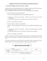
12.1 The power is not supplied.
Power plug is disengaged.
Insert the plug in the outlet.
↓
Circuit breaker is tripped.
Remove the cause and reset the breaker.
↓
Rated voltage cannot be obtained at the outlet.
Use another outlet.
↓
Checking of
outside conditions
It improves when the post processing equipment is
removed.
Investigate the post processing equipment.
↓
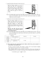
Connectors are disengaged.
・
Inlet
・
Noise filter
・
Power switch
・
Circuit breaker
・
Terminal board
・
Trans harness
Engage the connector.
↓
Remove the cover
on the
anti-operator’s
side.
Rated voltage cannot be detected at the terminal board. Check the harness around the power supply.
↓
Connector is disengaged.
Engage the connector.
↓
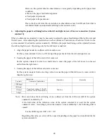
At the operation circuit board CN-10,
AC20V between pins 1 an3
AC7V between pins 4 and 5
AC7V between pins 5 and 6 cannot be detected.
The power transformer is faulty.
↓
The situation remains the same after all connectors
except one at the operation circuit board CN-10 are
removed.
The operation circuit board is faulty.
↓
Remove the cover
on the operator
side.
Check which connector is it to disable the machine
from starting up when it is removed.
Replace the relevant harness assembly.
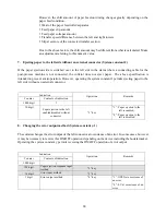
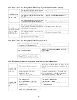
12.2 Paper is not fed though the CHECK key is pressed (Main motor does not rotate).
Back door is open. (The DOOR lamp flashes)
Close the back door.
↓
Paper is fully stacked.
(The EJECT lamp flashes)
Remove the stacked paper.
↓
Counter displays
[Err ].
Paper jam at paper feed section.
(Jam lamp and station lamp flash red)
Removed the jammed paper.
↓
Crisscross motor is locked.
(The CRISSCROSS lamp flashes).
Refer to “12.9 Crisscross does not work.”
↓
Counter displays
[LOCK].
Lifting motor is locked. (Station lamps flash
red like flowing up and down)
Refer to “12.6 Paper feed table does not rise”.
↓
Refer to “12.7 Main motor does not rotate”.
Содержание FC-10
Страница 2: ... 1 1 ...
Страница 14: ...13 6 WIRING DIAGRAM ...
Страница 15: ...14 7 CIRCUIT BOARD DIAGRAM 7 1 Operation board ...
Страница 16: ...15 7 2 Speed control circuit board ...
Страница 18: ...17 9 DIAGRAM FOR BELT INSTALLATION ...


