29
However, the ejected sheet-to-sheet distance varies greatly depending on the paper feed
condition.
•
Wear of the paper feed roller/separator
•
Feed paper slip amount
•
Feed paper collapse amount
Due to the above factors, the ejected sheet-to-sheet distance may be different from what is
calculated. Make an adjustment referring to this numeric value.
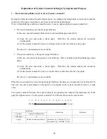
6. Adjusting the paper feed timing between the left and right towers at 2-tower connection (System
constant S)
When 2 collators are connected, it may be necessary to adjust the paper feed timing of the right tower and
the left tower. After adjusting the ejected sheet-to-sheet distance of each station of each tower (refer to the
system constant G), adjust the system constant S. With this, the paper feed timing can be adjusted between
the left and right towers. Operating only by the left tower is enabled.
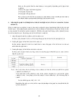
1. Align the paper heads of a collated set from each tower
Set the system constant S value to 170 to align the paper heads from the left and right towers.
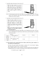
2. Causing the paper of the left tower to first come out
Set the system constant S value to a small value to cause the paper of the left tower to come out
earlier than the right tower.
3. Causing the paper of the left tower to later come out
Set the system constant S value to a large value to cause the paper of the left tower to come out later
than the right tower.
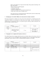
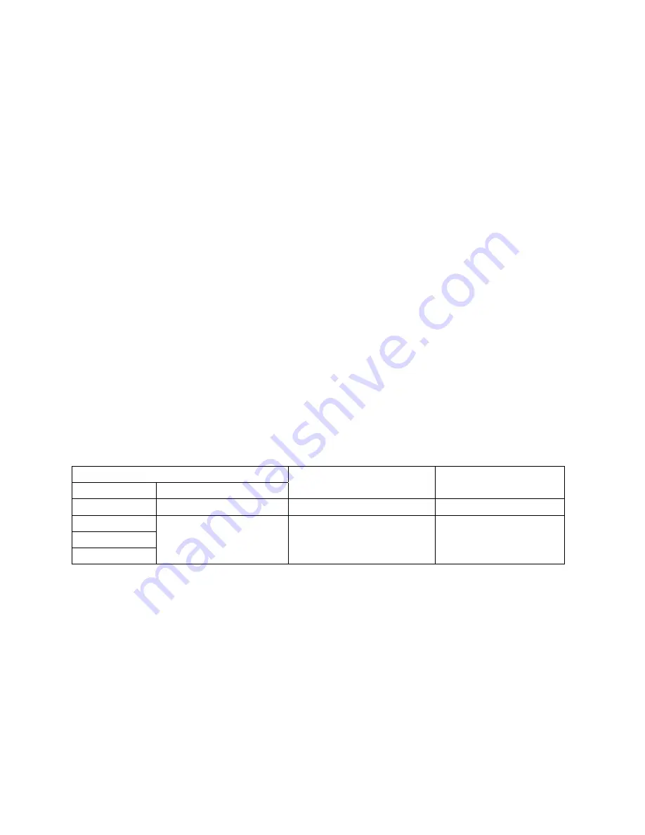
Indication
Counter Contents
of
indication
Operation Remarks
1000 digit
S
-
100 digit
10 digit
1 digit
Paper feed timing of the left
tower at 2-tower connection
Ten-key
Note: How much does the feed timing of one collated set from the left tower shift if the system
constant S is shifted by 1?
A ten-fold value of the reference value of the system constant G is used for the system
constant S value. Accordingly, when the numeric value is shifted by 1, the following shift is
caused.
For the 60 Hz region: 0.02
"
×
10 = 0.2
"
Regarding this value, an error will be caused depending on the paper feed condition like the
system constant G.
Содержание FC-10
Страница 2: ... 1 1 ...
Страница 14: ...13 6 WIRING DIAGRAM ...
Страница 15: ...14 7 CIRCUIT BOARD DIAGRAM 7 1 Operation board ...
Страница 16: ...15 7 2 Speed control circuit board ...
Страница 18: ...17 9 DIAGRAM FOR BELT INSTALLATION ...


