


Page 22
ADJUSTMENT
The miter scale can be easily read, showing miter angles
from 0° to 52° to the left, and 0° to 60° to the right. The miter
saw table has ten of the most common angle settings with
positive stops at 0°, 15°, 22.5°, 31.6°, 45° and 60° (right).
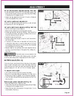
90° (0°) Bevel pointer adjustment (Fig. 12d-12e)
•
When the blade is exactly 90° (0°) to the table, loosen two
bevel pointer screws (G) (on each side) using the Phillips
screwdriver on the blade wrench.
•
Adjust two bevel pointers (H) to the “0” mark on the bevel
scale and retighten the screws.
45° Left & right bevel adjustment
If the 90° (0°) bevel have been set correctly, you do not need
to adjust the 45° left and right bevel.
48° Left & right bevel adjustment (Fig. 12d-12e)
• Set the miter angle to zero degrees.
• Remove the sliding fence and work piece clamp.
•
Pulling out the bevel detent pin (B) (Fig. 12d) toward the
front of the machine and loosen two bevel lock levers,
then tilt cutting arm to the 48° left.
• Tighten two bevel lock levers.
•
Using a combination square, check to see if the blade is
48° to the table.
•
To adjust, turn the screw (J) (located on the left of the
cutting arm) clockwise or counter-clockwise with 10mm
wrench/adjustment wrench or 3mm hex key (not included)
until the blade is 48° to the table.
•
Repeat steps for the right bevel 48° bevel adjustment only
turn the screw (K) (located on the right of the cutting arm).
(Fig. 12e)
To adjust miter angles
• Lift up the miter lock lever (A) to unlock the table.
•
Move the turntable while pushing down the miter latch
button (B) to align the pointer (C) to the desired degree.
•
Lock the table into position by pressing down on the miter
lock lever (A).
Miter angle pointer adjustment (Fig. 13)
• Move the table to the 0° positive stop.
•
Loosen the screw (D) that holds the pointer with the Phillips
screwdriver on the blade wrench.
•
Adjust the red line on the pointer (C) align to the 0° mark
and retighten the screw.
WARNING:
The work piece clamp assembly and
sliding fence will interfere with blade guard assembly
or motor when tilting the cutting head to 48° left or right.
FIG. 12d
FIG. 12e
FIG. 13
MITER SCALE (FIG. 13)
To lock
To unlock
G
H
B
J
K
A
D
C
H
H
H
B
G
B
G
G
Содержание 240-0028
Страница 44: ......


