Section 13: Microprocessor Computer and Control –Theory of Operation
13-12
13.7.10 CPU Timing Signals
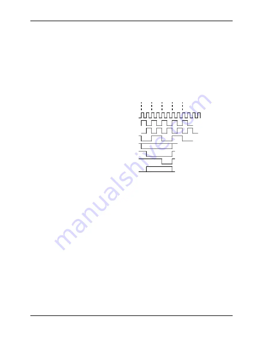
The 386EX runs from a 40 MHz crystal oscillator and the main timing is derived
from this clock. It is called CLK2. Inside the CPU, CLK2 is divided by two,
generating two new clocks, PH1 and PH2. Each T state is made up of one PH1
and one PH2 clock. There are a minimum of two T states per cycle. Each wait
state is one T state long (50 nanosecond) Therefore, adding wait states is adding
50 nanoseconds for each additional T2 states.
13.7.11 CPU Signals
Various signals change at various times within a cycle, and the generic timing is
shown below. Some of the key signals are ADS#, M/IO#, D/C#, W/R#, WR#,
RD#, CS0-CS6#, BLE#, and BHE#. Typical control circuits will look at ADS
#
at the end of PH2 and make decisions at this time. See Figure 13-7.
40MHZ
T1
T2
T1
T2
PH1
PH2
ADS#
W/R,BLE#,BHE#,CSO:6#,
UCS#,D/C#,M/IO,A1:25
RD#,WR#
LBA#,READY#
D0:15
Figure 13-7: CPU Signals
13.8 DRAM Control
The DRAM control consists of one 256kx16 DRAM chip, three 74ACT157
address mux chips, address resistors, and the FPGA control circuit.
The
CS6
*
(* = # = a low true signal) signal has been assigned to the DRAM
memory address space: 0-3FFFF words, or 0-7FFFF bytes. The CS6
*
control
register in the chip select unit (CSU) must be programmed for one wait state.
Since the data bus is 16 bits wide and the DRAM is a x16 part, most transfers
will be of the 16-bit variety. However, eight-bit transfers are allowed and
provisions have been made for byte addressing. This is done by using the upper
and lower cas signals, UCAS and LCAS.
13.8.1 DRAM Signals
For the DRAM design we must generate six signals, RAS#, UCAS#, LCAS#,
DRAMOE#, DRAMWR#, and CASADREN. All of these signals are generated
in the FPGA from the 386EX signals, ADS#, CS6#, M/IO#, D/C#, WR#, and
RD#.
Since the CSU is programmed for one wait state, the CSU generates the
READY
#
signal, which terminates the transfer.
Содержание NELLCOR NPB-4000
Страница 66: ... THIS PAGE INTENTIONALLY LEFT BLANK ...
Страница 68: ...Section 7 Spare Parts 7 2 Figure 7 1 NPB 4000 C Top Assembly Drawing ...
Страница 70: ...Section 7 Spare Parts 7 4 Figure 7 2 NPB 4000 C Front Case Assembly Diagram Sheet 1 of 2 ...
Страница 72: ...Section 7 Spare Parts 7 6 Figure 7 3 NPB 4000 C Front Case Assembly Diagram Sheet 2 of 2 ...
Страница 74: ...Section 7 Spare Parts 7 8 Figure 7 4 NPB 4000 C Rear Case Assembly Diagram Sheet 1 of 2 ...
Страница 76: ...Section 7 Spare Parts 7 10 Figure 7 5 NPB 4000 C Rear Case Assembly Diagram Sheet 2 of 2 ...
Страница 78: ...Section 7 Spare Parts 7 12 Figure 7 6 NPB 4000 C Power Supply Heat Sink Assembly Diagram ...
Страница 80: ... THIS PAGE INTENTIONALLY LEFT BLANK ...
Страница 96: ... THIS PAGE INTENTIONALLY LEFT BLANK ...
Страница 114: ... THIS PAGE INTENTIONALLY LEFT BLANK ...
Страница 140: ... THIS PAGE INTENTIONALLY LEFT BLANK ...
Страница 178: ...Section 14 Main Color Board Digital Theory of Operation 14 38 Figure 14 14 NPB 4000C Color Motherboard Block Diagram ...
Страница 180: ... THIS PAGE INTENTIONALLY LEFT BLANK ...
Страница 192: ... THIS PAGE INTENTIONALLY LEFT BLANK ...
Страница 208: ... THIS PAGE INTENTIONALLY LEFT BLANK ...
Страница 210: ... THIS PAGE INTENTIONALLY LEFT BLANK ...
Страница 211: ...Section 17 Drawings 17 3 Figure 17 1 MP 205 PCB Schematic Sheet 1 of 2 ...
Страница 212: ...Section 17 Drawings 17 5 Figure 17 2 MP 205 PCB Schematic Sheet 2 of 2 ...


