17
GB
W ARNING
The elec tric compress ors mus t be c onnect ed t o a power soc ket
that is saf eguarded by a s uitable differential s witch (magneto
thermal s witch).
ADJUSTING THE W ORKING PRESSURE
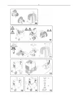
(fi g. 11) It is not
always necess ary t o us e the maxi mum wor king pressure, on the
contrar y t he pneumatic tool usually requires l ess press ure. Adjust
the wor king press ure acc urat ely i n compress ors provided with
pressure regulat ors. Release t he knob of the pressure regulat or by
pulling it outwards, adjus t the pr essure t o t he desired value by
turning the knob cloc kwis e to increas e it and anti-clockwise to
decreas e it. O nce t he ideal pr essure has been reac hed, bloc k the
knob by pus hing it downwards (fig. 11). In the case of pressure
regulators supplied wit hout a gauge, t he calibrati on pressure may
be s een on t he graduat ed scale situated on t he c asing of the actual
regulator. I n t he cas e of pr essure r egulators s upplied wit h a gauge,
the calibr ation pressure may be seen on t he act ual gauge.
WARNING: Some press ure regulat ors do not have “pus h to l oc k”,
theref ore si mpl y t urn t he knob t o adjust the press ure.
MAINTENANCE
Befor e ser vicing the compr essor make sure that:
-
the mai n line ON/OFF s witch is on «0».
-
the pressure switc h or the line s witc h is on «0».
-
there is no pr essure in the air tank ( onl y f or model with t ank)
.
The c ompressor generat es c ondens at e t hat accumulates in the
tank
.
The condensat e must be drained from the tank at least once
a wee
k
by opening the discharge tap (fig. 12) underneat h the tank
(only fo
r
model with tank)
.
Be c aref ul if there is any compr essed
air withi n t he c ylinder as th
e
water c ould burst out with some force.
Recommended pressur e 1
÷
2 bar max
.
RECOMMENDED MAINTENANCE
In units
F
wit h 2 poles , replace the whole c onnec ting rod unit every
700 hours of operati on.
In units
F
and FB
wit h 4 poles , repl ace t he whole c onnecting rod
unit ever y 1500 hours of operati on. I n units GMS and VS, replace
the slidi ng bloc ks and the compressi on ring every 1500 hours of
operation.
LUBRICATING THE BEARING S
All the bearings are lubricat ed with grease f or life wit h the
exc eption of the roller c asing fitted on the connecting rod side of
the GMS and VS units whic h is to be was hed wit h sol vent and re-
lubricated with “Kluber Barrierta L 55/2” greas e every 1500 hours
of operation (white greas e). The greas e must completel y fill the
spaces bet ween t he rollers; exc ess lubricant will be expelled during
the i nitial hours of operation.
CLEANING THE FILTER (F-
FB
-ECU-GMS-VS Series-AIRCLIK-F
1)
It is advisabl e to dis mantle t he suc tion filt er ever y 50 hours of use
and to clean t he fi ltering el ement by blowing it wit h compr essed
air, or replac e it if the el ement pointed out by t he arrow is clogged.
HOW TO PROCEED W HEN TRIVIAL ANOMALI ES
ARE ENCOUNTERED Loss of air from the valve underneath
the pressure switch (onl y model with tank)
This inconveni enc e is due to the imperf ect s eal of t he non-return
val ve
;
pr oceed as follows: (fig. 13)
.
Releas e all t he pressure from
the tank
.
Remove the panelling by unscrewing the four securing
screws and lif
t
it. (fig. 13-14) (
F 1 and AIRCLIK
)
.
Unscrew the
hexagonal head of t he val ve (A)(fig.15)
.
C arefull y clean the small
rubber dis k (B) and also its seat (fig.15)
.
Re-fi t ever yt hing
accurat ely
.
Loss of air (F-GMS-VS Series)
This may be due t o the poor seal of one of the fittings. Chec k all
the fi ttings by wetting t hem with s oapy wat er.
The compressor runs but fail s to load
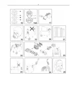
F-GMS-VS series compr essors: (fig.16)
-
This may be due t o a breakage of t he val ve, or a gas ket (B1-
B2). Replace the damaged c omponent.
-
This may be due to a breakage of the valves (C1-C2), or a
gasket
(B1-B2). Repl ace t he damaged component (fig.16B). AirClik-F
1 series (fig. 16A):
-
This may be due to the breakage of t he val ves (C1 - C2) or of
the gas ket (B1). Repl ace t he damaged part (fig. 16A).
The compressor f ails to start
If the compress or has difficult y in s tarting, make sure t hat : -the
mains volt age c orresponds to that indicated on the dat a nameplate
(fi g. 8)
- electrical ext ension cables with uns uitable cross-secti on or
length ar e not used.
-
the room in which the compress or is running is not too cold
(below 0°C)
-
the electric line is efficient (plug connected correctl y, magneto
thermal s witch, fus es not blown)
The compressor f ails to stop (onl y with tan k)
if the compr essor f ails to stop when the maxi mum pressure is
reached, the tank saf et y val ve will trip. Contact t he nearest
aut horised ser vice c entre for t he repairs.
W ARNING
-
Do not unscrew any connec tions wit h t he t ank when under
pressure for any reason whatsoever. Al ways make s ure t hat
the tank is depressurised bef orehand.
-
Do not drill, weld or intentionall y deform t he compressed air
tank.
-
Do not carry out any operati ons on the compress or bef ore it
has been unpl ugged from t he power s oc ket .
-
The room temperat ure f or its c orrect efficienc y is: 0°C +25°C
(MAX 45°C).
- Do not direct j ets of wat er or flammabl e liquids over t he
compressor.
-
Do not plac e fl ammable objec ts near t he c ompress or.
-
When st opped t emporarily during its use, tur n the pressure
switch or t he ON/OFF s witc h t o position «0» (OFF) (t urned-
off).
-
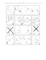
Never direct the jet of air towards peopl e or ani mals (fig. 24).
-
Do not transport the compr essor when the tank is pr essurised.
-
Be aware that s ome c omponents of the c ompressor s uch as
the head and delivery hos es may r each high t emperat ures,
theref ore do not touch the t o avoid getti ng burned (fig. 10).
-
Transport t he compress or by lifting or pulling it with the
appropriate grips or handl es (fig. 5 - 6).
-
Children and animals must be kept away from t he area in
which t he mac hine is running. If the compress or is used f or
painti ng: a) Do not work in closed areas or near free flames b)
Make sure t hat t he area in whic h you are wor king has a good
change of air c) Protect nos e and mouth usi ng an appropriate
mas k (fig. 18).
-
Do not us e t he c ompressor if the elec tric cable or t he plug is
damaged.
-
Contac t the neares t aut horised servic e centr e for the
replacement with an original component .
-
If it is plac ed on a shelf or a surfac e t hat is rais ed off t he
ground, it must be sec ured appropriat el y t o pr event it fr om
tipping of f when runni ng.
-
Do not insert objects or your hands inside the saf et y grating to
avoid physical damage and also damage t o the compress or
(fig. 19).
-
Do not use t he compress or to threaten people or ani mals to
avoid s erious i njuries.
-
Always unplug the compressor from the power soc ket when
you have finished using it.
ELECTRIC COMPRESSOR MODEL (GMS-VS-AIRCLIK-F 1-F)
Maxi mum running press ure: 8.5 bar
Maxi mum wor king press ure: 8 bar
ELECTRIC COMPRESSOR MODEL (FB 210)
Maxi mum running press ure: 10. 5 bar
Maxi mum wor king press ure: 10 bar
NOTE:
The c ompressor t anks have been manufact ured in c omplianc e with
th
e
87/ 404/EC Directi ve f or the European mar ket
.
The
compressors have been manufac tured in c omplianc e with th
e
98/ 37/ EC Directive f or the European mar ket
.
Содержание AC1300
Страница 4: ...4 ...
Страница 5: ...5 ...
Страница 6: ...6 ...
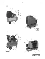
Страница 7: ...7 FX ECU GMS S ECU FB 210 ...
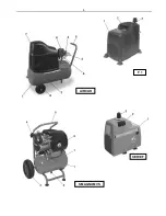
Страница 8: ...8 F 1 AIRCLIK SERIE F S MAGNUM VS ...
Страница 54: ...Cod 734 637 0000 02 2008 ...

