44
IGNITER REPLACEMENT
The igniter system on the MagnuM appliances’ is an integral part of the wiring system. If the igniter is
shorted out, the wiring must be disconnected in order for the unit to operate. If the wires are by-passed it
will cause the stove to short out and blow a fuse. It is recommended that once a season the igniter is
checked for proper operation and replaced if it does not glow red.
The igniter assembly is threaded, turn counter
clockwise to loosen. You will be able to slide the
igniter out the back if the end of the igniter in the
repot is not deformed. If the igniter will not slide
out the back, you will need to work the igniter back
and forth to dislodge any buildup.
ove the firepot from the unit to access the
igniter end. When installing the new igniter, hand
tighten the igniter and then apply slight pressure to
secure the threads. Do not over tighten the igniter
assembly.
If you over tighten the igniter assembly it may ruin
the igniter. Crimp and attach the terminal ends to the wiring harness. If you do not have a terminal
crimping tool, you will need to get one from a hardware store. Igniters are a consumable item and will
need to be replaced periodically.
Do
not attempt to take the igniter out of the unit while the unit is plugged into power or if the
igniter is hot.
Access to the igniter assembly, can be
made by opening the left side panel.
The power must be disconnected, check
that you do not pull on the wiring, when
taking out the circuit board. Take
special care not to cut yourself or
damage wiring.
Use two (2) pliers or needle nose pliers
to take the wire terminals apart. Be
careful not to pull the wire out of the
terminal ends as they are tight.
fi
Rem
Ignitor
Wires for Igniter
Содержание Winchester WINACI
Страница 21: ...21 MAGNUM WIN INSERT INSTALLATION ...
Страница 25: ...25 ...
Страница 26: ...Fireplace Insert Shroud Installation Diagram 26 ...
Страница 27: ...27 Thermostat wire connection Low voltage thermostat Molex Plug 24 volt thermostat hookup ...
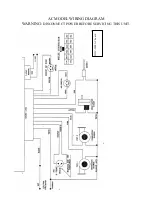
Страница 41: ...AC MODEL WIRING DIAGRAM WARNING DISCONNECT POWER BEFORE SERVICING THIS UNIT 41 DHC 3000 AC board ...
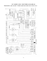
Страница 42: ...42 DC MODEL DDC 3000 WIRING DIAGRAM WARNING DISCONNECT POWER BEFORE SERVICING THIS UNIT ...

